- 44 -
one Recloser on the power supply side, only the Recloser experienced a fault is set to
perform the opening operation.
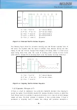
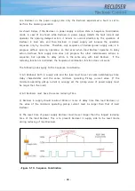
As shown below, if the Recloser in power supply is Active state in Sequence Coordination
mode, in case of line fault, while Recloser in power supply detects the fault current and
operates the opening delayed action, it returns to normal situation by the operation of
Recloser in load side, and then Recloser in power supply will increase the operation
sequence only by one time. Therefore, only sequence of Recloser(power supply side) is in
progress without opening operation, so that even when load Recloser operates to delay
action, Recloser from supply side does not progress the other instantaneous actions in
sequence, but operates to delay action in the same way with load Recloser. If the
reclosing function is restrained, the Sequence Coordination function does not work.
The following rules apply to the Sequence coordination
1) All Reclosers both in supply side and the load must be set at same instantaneous time,
delay characteristics and the same minimum operating Pickup current value. (If the
minimum operating pickup current is wrongly set, the pickup value of power supply must
be larger than the load)
2) All Reclosers must have the same reclosing Time.
3) Recloser in supply should resume 100ms or more of delay time than load Recloser, or
the value of the minimum operating pickup current must be larger than that of load
Recloser.
4) The reset time of power supply Recloser must be set longer than the longest reclosing
time of the load Recloser. This is to prevent Recloser in supply side to be reset mode
during reclosing of load Recloser.
<Figure 5-13> Sequence Coordination
Summary of Contents for RECLOSER
Page 1: ...User Manual Document Version 1 5 Feb 28 2019 http powersys kr http www powersys kr...
Page 14: ...8 3 5 Mechanical Performance and Size Weight 3 5 kg FRONT VIEW Figure 3 1 Front View...
Page 15: ...9 SIDE VIEW 343 00 310 00 91 00 Figure 3 2 Side View...
Page 16: ...10 TOP VIEW 84 0 260 0 225 0 1 0 0t Figure 3 3 Top View...
Page 17: ...11 REAR VIEW 180 0 120 0 Figure 3 4 Rear View...
Page 22: ...16 Controller PCB 215 00 103 90 121 10 112 50 112 50 235 00 205 00 Figure 3 8 Controller PCB...
Page 69: ...63...
Page 71: ...65 Example configuration file...
Page 73: ...67 2 TC Curve 1 4 100 101 10 1 100 101 102 Time sec Current In Multiplies of Setting 1 2 3 4...
Page 74: ...68 3 TC Curve 5 8 100 101 10 1 100 101 102 Time sec Current In Multiplies of Setting 5 6 7 8...
Page 77: ...71 6 TC Curve A D 100 101 10 1 100 101 102 Time sec Current In Multiplies of Setting A B C D...
Page 78: ...72 7 TC Curve E M 100 101 10 1 100 101 102 Time sec Current In Multiplies of Setting E K L M...
Page 79: ...73 8 TC Curve N T 100 101 10 1 100 101 102 Time sec Current In Multiplies of Setting N P R T...
Page 80: ...74 9 TC Curve V Z 100 101 10 1 100 101 102 Time sec Current In Multiplies of Setting V W Y Z...


