- 55 -
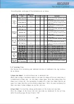
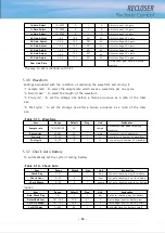
Item
Range
Default
Step
Unit
Explanation
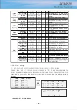
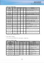
Max Op Count
1000~10000
2000
1
Set the type of the VI used in the
recloser
Alarm Level
0~100
45
1
%
Set alarm level for residual contact
wear
Duty Factor A
0~100
100
1
%
Set duty factor for A phase’s VI
Duty Factor B
0~100
100
1
%
Set duty factor for B phase’s VI
Duty Factor C
0~100
100
1
%
Set duty factor for C phase’s VI
Clear Wear Info
Delete save wear information in
backup memory
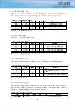
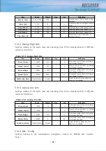
5.3.12. Analog High Alm
Settings relating to the alarm level and operating time of the Voltage/Current’s THD(Total
Harmonic Distortion).
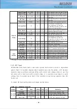
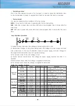
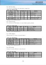
<Table 5-17> Analog High Alm
Item
Range
Default
Step
Unit
Explanation
Phase Current
1~16000
400
1
A
Set phase current level for Analog
High Alarm function
Ground Current
1~16000
400
1
A
Set ground current level for Analog
High Alarm function
Phase Voltage
1~38000
13200
1
V
Set phase voltage level for Analog
High Alarm function
System Power
1~54000
5280
1
kV
Set system power level for Analog
High Alarm function
Enable High Alarm
Disable/Enable
Disable
Select whether Analog High Alm
function is available
5.3.13. Analog Low Alm
Settings relating to the alarm level and operating time of the Voltage/Current’s THD(Total
Harmonic Distortion).
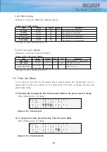
<Table 5-18> Analog Low Alm
Item
Range
Default
Step
Unit
Explanation
Phase Current
1~15999
110
1
A
Set phase current level for Analog
Low Alarm function
Ground Current
1~15999
110
1
A
Set ground current level for Analog
Low Alarm function
Phase Voltage
1~37999
510
1
V
Set phase voltage level for Analog
Low Alarm function
System Power
1~53999
0
1
kV
Set system power level for Analog
Low Alarm function
Enable Low Alarm
Disable/Enable
Disable
Select whether analog low alm
function is available
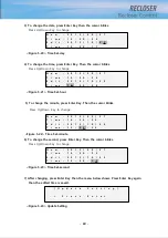
5.3.14. Misc. Config
Settings relating to the miscellaneous config(Door contact, AC POWER LED, Insulator
Type...).
Summary of Contents for RECLOSER
Page 1: ...User Manual Document Version 1 5 Feb 28 2019 http powersys kr http www powersys kr...
Page 14: ...8 3 5 Mechanical Performance and Size Weight 3 5 kg FRONT VIEW Figure 3 1 Front View...
Page 15: ...9 SIDE VIEW 343 00 310 00 91 00 Figure 3 2 Side View...
Page 16: ...10 TOP VIEW 84 0 260 0 225 0 1 0 0t Figure 3 3 Top View...
Page 17: ...11 REAR VIEW 180 0 120 0 Figure 3 4 Rear View...
Page 22: ...16 Controller PCB 215 00 103 90 121 10 112 50 112 50 235 00 205 00 Figure 3 8 Controller PCB...
Page 69: ...63...
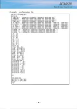
Page 71: ...65 Example configuration file...
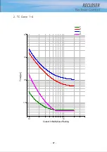
Page 73: ...67 2 TC Curve 1 4 100 101 10 1 100 101 102 Time sec Current In Multiplies of Setting 1 2 3 4...
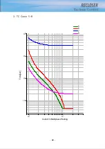
Page 74: ...68 3 TC Curve 5 8 100 101 10 1 100 101 102 Time sec Current In Multiplies of Setting 5 6 7 8...
Page 77: ...71 6 TC Curve A D 100 101 10 1 100 101 102 Time sec Current In Multiplies of Setting A B C D...
Page 78: ...72 7 TC Curve E M 100 101 10 1 100 101 102 Time sec Current In Multiplies of Setting E K L M...
Page 79: ...73 8 TC Curve N T 100 101 10 1 100 101 102 Time sec Current In Multiplies of Setting N P R T...
Page 80: ...74 9 TC Curve V Z 100 101 10 1 100 101 102 Time sec Current In Multiplies of Setting V W Y Z...

