- 24 -
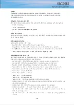
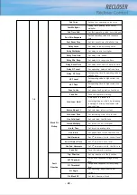
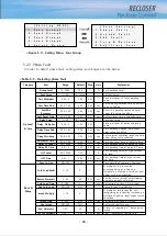
1~4
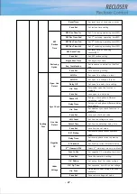
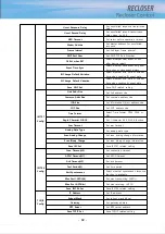
Fast Curve
Setting fast operating value curve
Fast Multiplier
Setting fast operating value control
multiplier
Fast Time Add
Set fast operating value time delayed
Fast Min Response
Set fast operating value min. response
time
Fast Reset Time
Set fast reset time of definite time
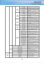
Delay Curve
Set delay curve-operating value
Delay Multiplier
Set delay control multiplier
Delay Time Add
Set delay time added
Delay Min Resp
Set delay min. response time
Delay Reset Time
Set delay reset time of definite time
Delay DT Level
Set operating value at definite time
Delay DT Time
Set operating time for operating value at
definite time
HCT Level
Set operating value at high current trip
level
HCT Time
Set operating time at high current trip
time
Func In Use
Set phase fault operation functions
Save Set
Save the operation setting
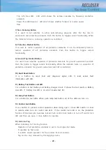
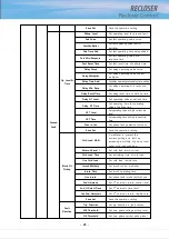
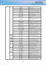
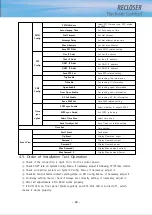
Block Flt
Pickup
Cold Load Multi
A multiplier to prevent the
mis-recognizing as a fault by increasing
a multiply of pick-up level under cold
load condition.
Return Normal I
Set cold load return current
Cold Load Time
Set restraining time of cold load
Use Cold Load
Set cold load Use/Not use
Inrush Multiply
Set inrush control multiplier
Inrush Time
Set inrush operating time
Use Inrush
Set phase fault inrush Use/Not use
2nd Harmonic
Set 2
nd
harmonic inrush control level
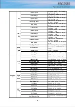
2nd_H Detect Time
Set 2
nd
harmonic time level
Use 2nd Harmonic
Set 2
nd
harmonic inrush Use/Not use
Save Set
Save the operation setting
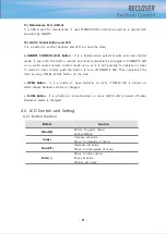
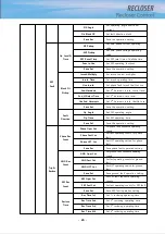
Fault
Direction
Trip Direction
Set trip direction in fault section
3V1 Threshold
Set positive sequence voltage pickup
level
3I1 Threshold
Set positive sequence current pickup
level
3I1 Angle
Set operating angle directional
current
Dir Block OC
Set fault direction block
Summary of Contents for RECLOSER
Page 1: ...User Manual Document Version 1 5 Feb 28 2019 http powersys kr http www powersys kr...
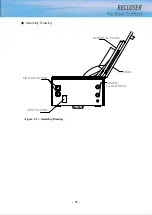
Page 14: ...8 3 5 Mechanical Performance and Size Weight 3 5 kg FRONT VIEW Figure 3 1 Front View...
Page 15: ...9 SIDE VIEW 343 00 310 00 91 00 Figure 3 2 Side View...
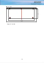
Page 16: ...10 TOP VIEW 84 0 260 0 225 0 1 0 0t Figure 3 3 Top View...
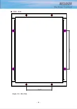
Page 17: ...11 REAR VIEW 180 0 120 0 Figure 3 4 Rear View...
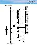
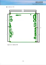
Page 22: ...16 Controller PCB 215 00 103 90 121 10 112 50 112 50 235 00 205 00 Figure 3 8 Controller PCB...
Page 69: ...63...
Page 71: ...65 Example configuration file...
Page 73: ...67 2 TC Curve 1 4 100 101 10 1 100 101 102 Time sec Current In Multiplies of Setting 1 2 3 4...
Page 74: ...68 3 TC Curve 5 8 100 101 10 1 100 101 102 Time sec Current In Multiplies of Setting 5 6 7 8...
Page 77: ...71 6 TC Curve A D 100 101 10 1 100 101 102 Time sec Current In Multiplies of Setting A B C D...
Page 78: ...72 7 TC Curve E M 100 101 10 1 100 101 102 Time sec Current In Multiplies of Setting E K L M...
Page 79: ...73 8 TC Curve N T 100 101 10 1 100 101 102 Time sec Current In Multiplies of Setting N P R T...
Page 80: ...74 9 TC Curve V Z 100 101 10 1 100 101 102 Time sec Current In Multiplies of Setting V W Y Z...

