- 28 -
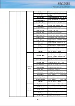
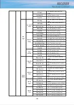
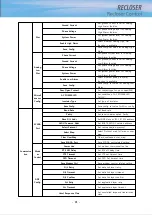
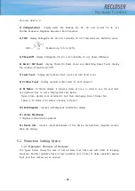
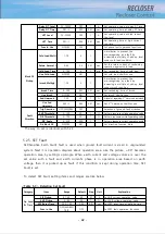
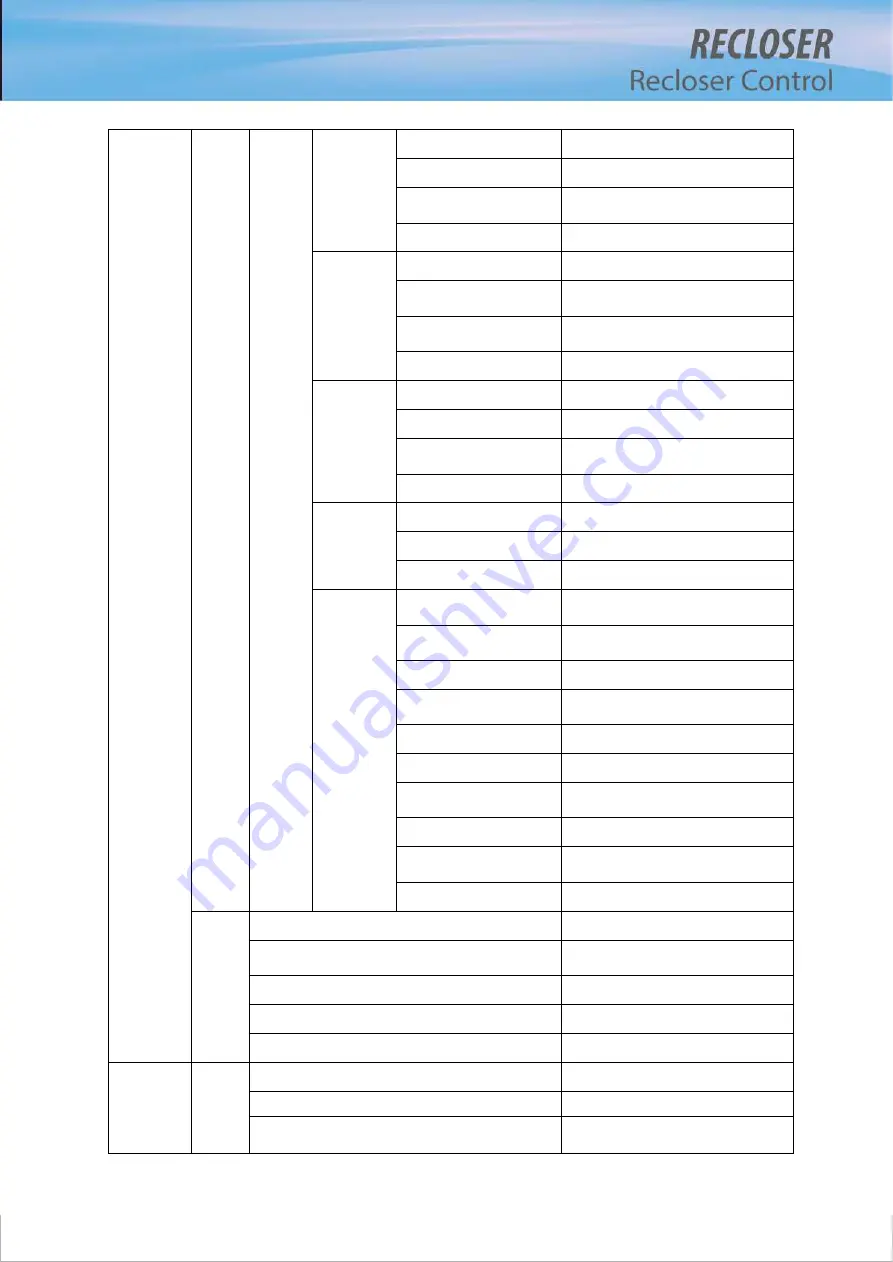
Over
Voltage
O-V Pickup
Set pickup level for over voltage
O-V Op Time
Set operation time for over voltage
Use Func
Set whether over voltage function is
available
Save Set
Save over voltage set value
Under
Frequency
U-F Pickup
Set pickup level for under frequency
U-F Op Time
Set operation time for under
frequency
Use Func
Set whether under frequency function
is available
Save Set
Save under frequency set value
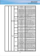
Over
Frequency
O-F Pickup
Set pickup level for over frequency
O-F Op Time
Set operation time for over frequency
Use Func
Set whether over frequency function
is available
Save Set
Save over frequency set value
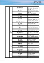
Close
Interlock
Live Load
Select whether live load is available
Sync Fail
Select whether sync fail is available
Save Set
Save close interlock set value
Loop
Automation
Loop Selection
Select operating mode for the
recloser
Deadbus Open Time
Set open time for determining
distribution line’s dead line state
Tie Sw Open Time
Set Open time for tie sw
Tie Sw Source
Select whether Tie sw source is ABC or
RST
Tie Sw Close Time
Set close time for tie sw
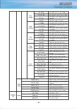
Rec Block Time
Set Reclosing Blocking Time
Enable Restore
Set whether restoration after clearing
fault
Rec Close Time
Set recloser closing time after open
Tie On delta I
Set delta I level to restore for Tie
recloser after fault
Save Set
Save loop automation set value
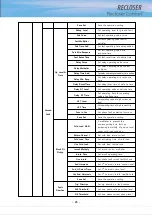
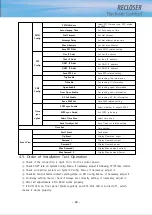
Select
Group
Primary Group
Select a group which will be actvated
Sel Auto Group
Select whether auto group function is
available
Reverse Group
Select a alternative group
Save Sel Group
Save select group set value
Default Fact Set
Set all settings to factory settings
Configurat-
ion
Analog
Line Config
Set 3P4W / 3P3W
Frequency
Set frequency(50/60Hz)
Rated Volt
Set rated voltage
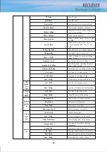
Summary of Contents for RECLOSER
Page 1: ...User Manual Document Version 1 5 Feb 28 2019 http powersys kr http www powersys kr...
Page 14: ...8 3 5 Mechanical Performance and Size Weight 3 5 kg FRONT VIEW Figure 3 1 Front View...
Page 15: ...9 SIDE VIEW 343 00 310 00 91 00 Figure 3 2 Side View...
Page 16: ...10 TOP VIEW 84 0 260 0 225 0 1 0 0t Figure 3 3 Top View...
Page 17: ...11 REAR VIEW 180 0 120 0 Figure 3 4 Rear View...
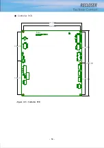
Page 22: ...16 Controller PCB 215 00 103 90 121 10 112 50 112 50 235 00 205 00 Figure 3 8 Controller PCB...
Page 69: ...63...
Page 71: ...65 Example configuration file...
Page 73: ...67 2 TC Curve 1 4 100 101 10 1 100 101 102 Time sec Current In Multiplies of Setting 1 2 3 4...
Page 74: ...68 3 TC Curve 5 8 100 101 10 1 100 101 102 Time sec Current In Multiplies of Setting 5 6 7 8...
Page 77: ...71 6 TC Curve A D 100 101 10 1 100 101 102 Time sec Current In Multiplies of Setting A B C D...
Page 78: ...72 7 TC Curve E M 100 101 10 1 100 101 102 Time sec Current In Multiplies of Setting E K L M...
Page 79: ...73 8 TC Curve N T 100 101 10 1 100 101 102 Time sec Current In Multiplies of Setting N P R T...
Page 80: ...74 9 TC Curve V Z 100 101 10 1 100 101 102 Time sec Current In Multiplies of Setting V W Y Z...

