- 48 -
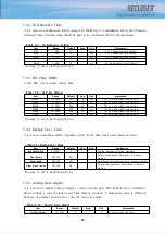
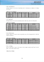
- “Tie SW open time”
This is the time required to open a “Tie Sw open” in order to repair the distribution lines
to the normal state, if power is supplied from both Tie Sw after the fault is recovered.
- “Tie Sw Source”
It is used to determine the conditions of Tie Sw closing.
BOTH
: If any loss for both side, it operates after Tie Sw closing time.
ABC
: ABS side is power side, and when RST side is de-energized, then it closes after the
close time.
RST
: RST side is power side, when RST side is de-energized, then it closes after the close
time.
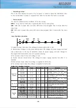
Loop Operation procedure
Tie
REC
MID
REC
Feeder
REC
CB
CB
1) Feeder recloser trips when the voltage at power supply side is lost.
2) Mid recloser changes to Alt group setting when the voltage of power supply and load
side is dead due to the trip of protection device at power supply, and also changes to
the single shot mode which does not operate reclosing.
3) Tie recloser closes if one side voltage is lost.
4) Feeder recloser closed when the voltage at power supply become live after it is
repaired.
5) Mid recloser closes when the voltage is supplied to both side.
6) Tie recloser opens when the voltage is supplied to both ends.
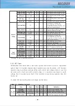
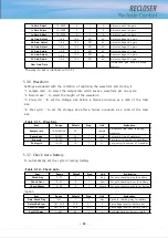
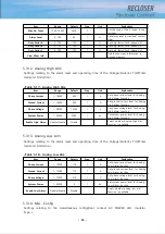
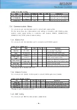
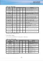
<Table 5-5> Auxiliary Function
Category
Item
Range
Default
Step
Unit
Explanation
Open Line
Detect
Volt On
50~90
90
1
%
Voltage setting to reset
phase
loss(standard on rating voltage)
Volt Off
35~75
75
1
%
Voltage
setting
to
set
phase
loss(standard on rating voltage)
Delay Off
0.1~30
30
0.1
sec
If voltage is kept under volt off
during delay time
Use Func
NO/YES
YES
Show whether open line detect
function is available
Sync Check
Phase Off
5~60
5
1
°
degree setting to check phase sync
Delay Time
0.1~30
30
0.1
sec
delay time setting to check phase sync
Use Func
NO/YES
YES
Show whether sync check function is
available
Live Line
Detect
Volt Level
10~90
30
1
%
Set voltage level monitoring operation
Detect Time
0.05~1
0.10
0.01
sec
Set voltage level operating time
Negative
OC
I2/I1 Pickup
30~100%
50
1
%
Set negative current operating level
Delay Time
0.1~10
10.0
0.1
sec
Set negative OC operation time
I1 Threshold
5~200
10
1
A
Set Positive current threshold value
2
nd
Harmonic Blk
OFF/ALM/TRIP
OFF
Select 2nd Harmonic block/ non-block
Func In Use
OFF/ALM/TRIP
OFF
Set negative OC fault operation
functions, No Use/Alarm/Trip
Summary of Contents for RECLOSER
Page 1: ...User Manual Document Version 1 5 Feb 28 2019 http powersys kr http www powersys kr...
Page 14: ...8 3 5 Mechanical Performance and Size Weight 3 5 kg FRONT VIEW Figure 3 1 Front View...
Page 15: ...9 SIDE VIEW 343 00 310 00 91 00 Figure 3 2 Side View...
Page 16: ...10 TOP VIEW 84 0 260 0 225 0 1 0 0t Figure 3 3 Top View...
Page 17: ...11 REAR VIEW 180 0 120 0 Figure 3 4 Rear View...
Page 22: ...16 Controller PCB 215 00 103 90 121 10 112 50 112 50 235 00 205 00 Figure 3 8 Controller PCB...
Page 69: ...63...
Page 71: ...65 Example configuration file...
Page 73: ...67 2 TC Curve 1 4 100 101 10 1 100 101 102 Time sec Current In Multiplies of Setting 1 2 3 4...
Page 74: ...68 3 TC Curve 5 8 100 101 10 1 100 101 102 Time sec Current In Multiplies of Setting 5 6 7 8...
Page 77: ...71 6 TC Curve A D 100 101 10 1 100 101 102 Time sec Current In Multiplies of Setting A B C D...
Page 78: ...72 7 TC Curve E M 100 101 10 1 100 101 102 Time sec Current In Multiplies of Setting E K L M...
Page 79: ...73 8 TC Curve N T 100 101 10 1 100 101 102 Time sec Current In Multiplies of Setting N P R T...
Page 80: ...74 9 TC Curve V Z 100 101 10 1 100 101 102 Time sec Current In Multiplies of Setting V W Y Z...

