- 53 -
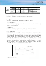
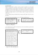
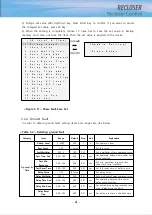
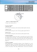
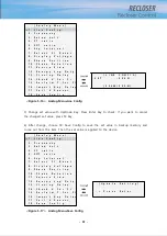
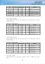
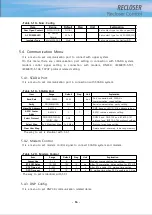
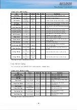
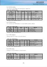
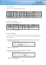
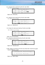
The way to set is identical with 5.3.1
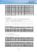
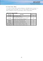
5.3.6. Waveform
Settings associated with the condition of capturing the waveform and storing it.
“1. sample rate” : to select the sample rate which saves a waveform per one cycle.
“2. Record size” : to select the length of the waveform.
“3. Pre-cycle” : to set the stotage size before a failure occurance as a ratio of the total
size.
“4. Post-cycle” : to set the stotage size after a failure occurance as a ratio of the total
size.
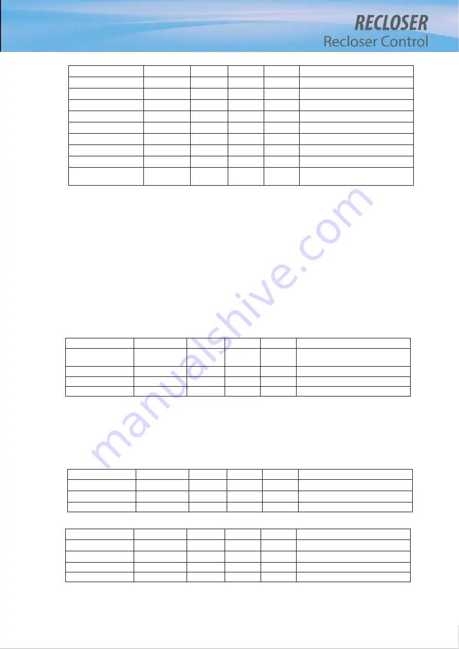
<Table 5-11> Waveform
Item
Range
Default
Step
Unit
Explanation
Sample rate
16/32/64/128
32
sample
Set sample rate when capturing
waveform
Record size
20~600
20
1
cycle
Set record size of waveform
Pre-cycle
10~50
10
1
%
Set pre-cycle number of waveform
Post-cycle
10~50
10
1
%
Set post cycle number of waveform
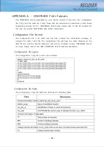
5.3.7. Check Auto Battery
To automatically set the cycle of testing battery.
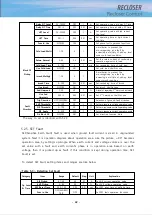
<Table 5-12> Check Auto
Item
Range
Default
Step
Unit
Explanation
Check Day
1~31
1
1
day
Set auto checking day for battery
Check Hour
0~23
0
1
hour
Set auto checking hour for battery
Check Minute
0~59
0
1
minute
Set auto checking minute for battery
*option
Item
Range
Default
Step
Unit
Explanation
Auto-Check Day
1~31
1
1
day
Set auto checking day for battery
Detect Batt-Low
18.7~24.0
21.6
0.1
V
Set voltage level for battery low
Cut-Off Voltage
18.7~23.0
20.8
0.1
V
Set voltage level for battery cutoff
Cut-Off Delay
1~600
60
1
s
Set delay time for battery cutoff
Ib Gain Adjust
10~2000
0
1
A
Adjust current Ib’s gain
Ic Gain Adjust
10~2000
0
1
A
Adjust current Ic’s gain
In Gain Adjust
10~2000
0
1
A
Adjust current In’s gain
Va Gain Adjust
1~66
13.2
0.01
kV
Adjust voltage Va’s gain
Vb Gain Adjust
1~66
13.2
0.01
kV
Adjust voltage Vb’s gain
Vc Gain Adjust
1~66
13.2
0.01
kV
Adjust voltage Vc’s gain
Vr Gain Adjust
1~66
13.2
0.01
kV
Adjust voltage Vr’s gain
Vs Gain Adjust
1~66
13.2
0.01
kV
Adjust voltage Vs’s gain
Vt Gain Adjust
1~66
13.2
0.01
kV
Adjust voltage Vt’s gain
Clear Gain Data
Delete save gain data in backup
memory
Summary of Contents for RECLOSER
Page 1: ...User Manual Document Version 1 5 Feb 28 2019 http powersys kr http www powersys kr...
Page 14: ...8 3 5 Mechanical Performance and Size Weight 3 5 kg FRONT VIEW Figure 3 1 Front View...
Page 15: ...9 SIDE VIEW 343 00 310 00 91 00 Figure 3 2 Side View...
Page 16: ...10 TOP VIEW 84 0 260 0 225 0 1 0 0t Figure 3 3 Top View...
Page 17: ...11 REAR VIEW 180 0 120 0 Figure 3 4 Rear View...
Page 22: ...16 Controller PCB 215 00 103 90 121 10 112 50 112 50 235 00 205 00 Figure 3 8 Controller PCB...
Page 69: ...63...
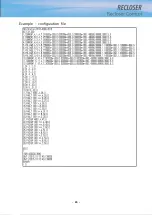
Page 71: ...65 Example configuration file...
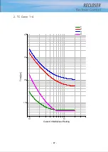
Page 73: ...67 2 TC Curve 1 4 100 101 10 1 100 101 102 Time sec Current In Multiplies of Setting 1 2 3 4...
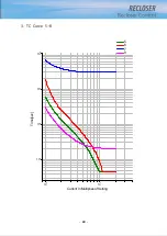
Page 74: ...68 3 TC Curve 5 8 100 101 10 1 100 101 102 Time sec Current In Multiplies of Setting 5 6 7 8...
Page 77: ...71 6 TC Curve A D 100 101 10 1 100 101 102 Time sec Current In Multiplies of Setting A B C D...
Page 78: ...72 7 TC Curve E M 100 101 10 1 100 101 102 Time sec Current In Multiplies of Setting E K L M...
Page 79: ...73 8 TC Curve N T 100 101 10 1 100 101 102 Time sec Current In Multiplies of Setting N P R T...
Page 80: ...74 9 TC Curve V Z 100 101 10 1 100 101 102 Time sec Current In Multiplies of Setting V W Y Z...

