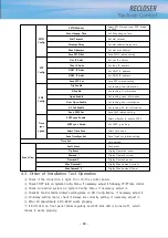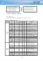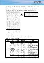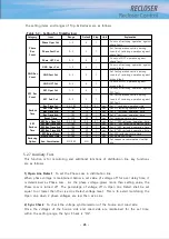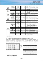
[ S e t t i n g
M E N U ]
→
1 . F u n c G r o u p 1
2 . F u n c G r o u p 2
3 . F u n c G r o u p 3
4 . F u n c
G r o u p 4
5 . S e l e c t
G r o u p
[ F u n c
S e t t i n g ]
→
1 . P h a s e
F a u l t
2 . G r o u n d
d
F a u l t
3 . S E F
F a u l t
4 . T r i p
&
R e c l o s e
5 . A u x i l i a r y
F u n c
- 38 -
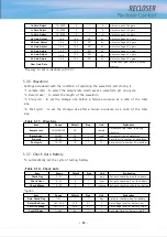
<Figure 5-7> Setting Menu- Func Group
5.2.3. Phase Fault
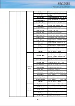
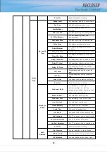
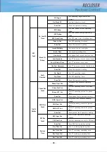
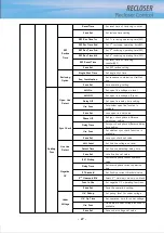
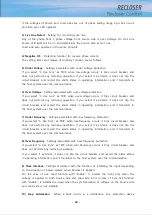
In order to detect phase fault, setting items and ranges are like below.
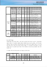
<Table 5-1> Detecting phase fault
Category
Item
Range
Default
Step
Unit
Explanation
Op Level
& Time
Pickup Level
10~2000
400
1
A
Set operation level
Fast Curve
1~50
A Curve
Set fast curve
Fast Multiplier
0.05~2
1.00
0.01
Set a multiplier of fast operating
curve.
Fast Time Add
0.00~1.00
0.00
0.01
sec
Set operating delayed time under fast
curve condition
Fast Min
Response
0.00~1.00
0.00
0.01
sec
Set min. operating response time
under fast curve condition
Fast Reset Time
0.00~1.00
0.00
0.01
sec
Set fast reset time of definite time
Delay Curve
1~50
B Curve
Set delay curve
Delay Multiplier
0.05~2
1.00
0.01
Set a multiplier of delay operating
curve.
Delay Time Add
0.00~1.00
0.00
0.01
sec
Set operating delayed time under
delay curve condition
Delay Min Resp
0.00~1.00
0.00
0.01
sec
Set minimum operating response time
under delay curve condition
Delay Reset Time
0.00~1.00
0.00
0.01
sec
Set delay reset time of definite time
Delay DT Level
25~10000
OFF
1
A
Set operating value at delay DT level
Delay DT Time
0.01~2
2.00
0.01
sec
Set operating time at delay DT time
HCT Level
25~10000
OFF
1
A
Set operating value at high current
trip level
HCT Time
0.01~1
0.04
0.01
sec
Set operating time at high current
trip time
Func In Use
NO/YES
YES
Set phase fault operation functions
Block flt
Pickup
Cold Load Multi
1~10
2
1
A multiplier to prevent the
mis-recognizing as a fault by
increasing a multiply of pick-up level
under cold load condition.
Return Normal I
0~30
0.3
0.01
sec
Set the return current of restraining
operation against cold load
Cold Load Time
0~180
3
1
min
Set restraining time of cold load
Use Cold Load
NO/YES
NO
Set cold load Use/Not use
Inrush Multiply
1~10
2
1
A multiplier to prevent the mis-
recognizing as a fault by increasing a
multiple of pick-up level under inrush
condition
Inrush Time
0~30S
0.02
0.01
sec
Set restraining time of Inrush
Use Inrush
NO/YES
NO
Set inrush Use/Not use
2nd Harmonic
1-50
20
1
%
A level of regarding 2
nd
harmonic as
inrush
Use 2nd Harmonic
0.02~1
0.02
0.01
sec
Set 2
nd
harmonics Use/Not use
Summary of Contents for RECLOSER
Page 1: ...User Manual Document Version 1 5 Feb 28 2019 http powersys kr http www powersys kr...
Page 14: ...8 3 5 Mechanical Performance and Size Weight 3 5 kg FRONT VIEW Figure 3 1 Front View...
Page 15: ...9 SIDE VIEW 343 00 310 00 91 00 Figure 3 2 Side View...
Page 16: ...10 TOP VIEW 84 0 260 0 225 0 1 0 0t Figure 3 3 Top View...
Page 17: ...11 REAR VIEW 180 0 120 0 Figure 3 4 Rear View...
Page 22: ...16 Controller PCB 215 00 103 90 121 10 112 50 112 50 235 00 205 00 Figure 3 8 Controller PCB...
Page 69: ...63...
Page 71: ...65 Example configuration file...
Page 73: ...67 2 TC Curve 1 4 100 101 10 1 100 101 102 Time sec Current In Multiplies of Setting 1 2 3 4...
Page 74: ...68 3 TC Curve 5 8 100 101 10 1 100 101 102 Time sec Current In Multiplies of Setting 5 6 7 8...
Page 77: ...71 6 TC Curve A D 100 101 10 1 100 101 102 Time sec Current In Multiplies of Setting A B C D...
Page 78: ...72 7 TC Curve E M 100 101 10 1 100 101 102 Time sec Current In Multiplies of Setting E K L M...
Page 79: ...73 8 TC Curve N T 100 101 10 1 100 101 102 Time sec Current In Multiplies of Setting N P R T...
Page 80: ...74 9 TC Curve V Z 100 101 10 1 100 101 102 Time sec Current In Multiplies of Setting V W Y Z...

