- 39 -
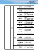
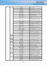
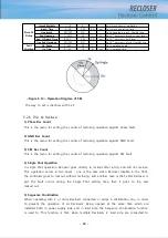
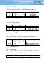
1) Fast Operation
This menu is for setting “FAST” among Recloser’s operation sequence
2) Delay Operation
This menu is for setting “Delay” among Recloser’s operation sequence
3) Delay DT Protection
This menu is for setting Delay Definite Time regardless of targeted section among
Recloser’s operation sequence
4) HCT Protection
This menu is for setting the protection against the high current trip of Recloser
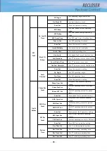
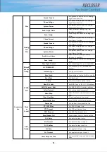
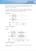
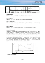
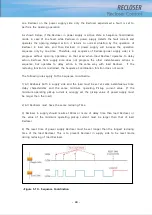
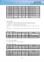
5) Cold load Operation
If a load has not been powered for a prolonged period, and when the power has again
resumed i.e. by input of circuit breaker, this can impose a higher current than the pickup
value of time-delay overcurrent protection, which could exceed normal settings. These
conditions can exists for an extended period and must not be interpreted as a fault. In
other words, this function is recognized as Cold load circumstance, when no current
measured in the Recloser is maintained for 5 minutes(300sec). If the measured current is
less than the multiples of pick-up, Recloser does not recognize it as a failure. If it is larger
than the multiples of pick-up, Recloser regards the situation as an actual fault, and
performs the same reclosing sequence same as normal operation.
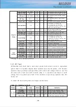
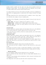
<Figure 5-8> ColdLoad
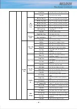
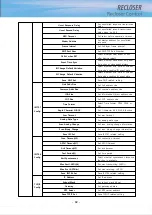
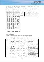
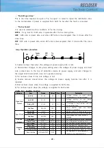
Fault
Direction
Trip Direction
OFF/FWD/REV
OFF
Selection of phase fault direction
3V1 Threshold
0~100
20
1
%
Set positive sequence voltage
operating value
3I1 Threshold
0~100
20
1
%
Set positive sequence current
operating value
3I1 Angle
0~359
300
1
°
Set positive sequence current
operating angle
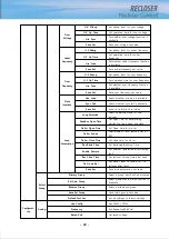
Dir Block OC
NO/YES
NO
Set direction function block
Summary of Contents for RECLOSER
Page 1: ...User Manual Document Version 1 5 Feb 28 2019 http powersys kr http www powersys kr...
Page 14: ...8 3 5 Mechanical Performance and Size Weight 3 5 kg FRONT VIEW Figure 3 1 Front View...
Page 15: ...9 SIDE VIEW 343 00 310 00 91 00 Figure 3 2 Side View...
Page 16: ...10 TOP VIEW 84 0 260 0 225 0 1 0 0t Figure 3 3 Top View...
Page 17: ...11 REAR VIEW 180 0 120 0 Figure 3 4 Rear View...
Page 22: ...16 Controller PCB 215 00 103 90 121 10 112 50 112 50 235 00 205 00 Figure 3 8 Controller PCB...
Page 69: ...63...
Page 71: ...65 Example configuration file...
Page 73: ...67 2 TC Curve 1 4 100 101 10 1 100 101 102 Time sec Current In Multiplies of Setting 1 2 3 4...
Page 74: ...68 3 TC Curve 5 8 100 101 10 1 100 101 102 Time sec Current In Multiplies of Setting 5 6 7 8...
Page 77: ...71 6 TC Curve A D 100 101 10 1 100 101 102 Time sec Current In Multiplies of Setting A B C D...
Page 78: ...72 7 TC Curve E M 100 101 10 1 100 101 102 Time sec Current In Multiplies of Setting E K L M...
Page 79: ...73 8 TC Curve N T 100 101 10 1 100 101 102 Time sec Current In Multiplies of Setting N P R T...
Page 80: ...74 9 TC Curve V Z 100 101 10 1 100 101 102 Time sec Current In Multiplies of Setting V W Y Z...

