3.7
MAINTENANCE
HONING PROCEDURE
1.
Wash the cylinder with solvent.
2.
Clamp the cylinder in a soft jawed vise by the exhaust port
studs.
3.
Place hone in cylinder and tighten stone adjusting knob
until stone contacts the cylinder walls (DO NOT
OVERTIGHTEN). Cylinders may be wet or dry honed
depending on the hone manufacturer's recommendations.
Wet honing removes more material faster and leaves a
more distinct pattern in the bore. Using a 1/2
"
(13 mm)
drill motor rotating at a speed of 300-500 RPM, run the
hone in and out of the cylinder rapidly until cutting tension
decreases. Remember to keep the hone drive shaft centered
to prevent edge loading and always bring the stone
approximately 1/2
"
(1.3 cm) beyond the bore at the end of
each stroke.
4.
Release the hone at regular intervals to inspect bore size
and finish.
HONING TO OVER SIZE (340/550/500 FUJI
ENGINES ONLY)
If cylinder wear or damage is excessive, it will be necessary to
oversize the cylinder using a new oversize piston and rings.
This may be accomplished by either boring the cylinder and
then finish honing to the final bore size, or by rough honing
followed by finish honing.
For oversize honing always wet hone using honing oil and a
coarse roughing stone. Measure the new piston at room
temperature (see piston measurement) and rough hone to the
size of the piston or slightly larger. Always leave .002
"
- .003
"
(.05 - .07 mm) for finish honing. Complete the sizing with fine
grit stones to provide the proper cross-hatch finish and
required piston clearance.
Inspect cylinder for taper and out-of-round. Taper or out-of-
round on the finished bore should not exceed .0004
"
(.002mm).
NOTE: Portable rigid hones are not recommended
for oversizing cylinders, cylinder boring, and finish
honing. The use of an arbor type honing machine is
recommended. Always check piston to cylinder
clearance and piston ring installed gap after boring/
honing is complete.
CLEANING THE CYLINDER AFTER HONING
It is very important that the cylinder be thoroughly cleaned
after honing to remove all grit material. Wash the cylinder in a
solvent, then in hot soapy water. Pay close attention to areas
where the cylinder sleeve meets the aluminum casting
(transfer port area). Use electrical contact cleaner if necessary
to clean these areas. Rinse thoroughly, dry with compressed
air, and oil the bore immediately with Polaris Premium 2
Cycle Lubricant.
NOTE: Always check piston to cylinder clearance
and piston ring installed gap after honing or boring
is complete.
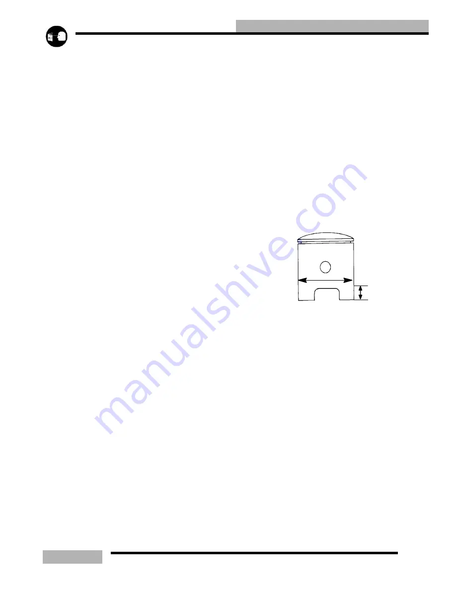
PISTON INSPECTION
Check piston for scoring or cracks in piston crown or pin area.
Excessive carbon buildup below the ring lands is an indication
of piston, ring or cylinder wear. For Liberty
t
engines,
measure piston outside diameter at a point 3/8
"
(10mm) up
from the bottom of the skirt at a 90
_
angle to the direction of
the piston pin. For Fuji engines, measure piston outside
diameter at a point that is 1/2
"
(12.7mm) up form the bottom
of the skirt at a 90
_
angle to the direction of the piston pin.
NOTE: The piston is measured at this point to
provide an accurate piston to cylinder
measurements.
Subtract this measurement from the minimum cylinder
measurement (90
_
to the pin) recorded previously when you
recorded the cylinder measurements. If clearance exceeds the
service limit, the cylinder should be re-bored and new pistons
and rings installed. Refer to piston to cylinder clearance limits
in the General Information section listed per model.
90
q
to pin
DOMESTIC ENGINES - Measure 3/8
s
(10.0mm)
up from bottom of skirt
FUJI ENGINES - Measure 1/2
s
(12.7mm) up
from bottom of skirt
Summary of Contents for SUPERSPORT 2006
Page 48: ...NOTES SPECIFICATIONS 1 48...
Page 55: ...2 7 GENERAL SAE TAP DRILL SIZES METRIC TAP DRILL SIZES DECMIAL EQUIVALENTS...
Page 60: ...2 12 GENERAL SPECIAL TOOLS...
Page 61: ...2 13 GENERAL...
Page 62: ...2 14 GENERAL...
Page 106: ...4 18 CARBURETION...
Page 139: ...6 27 ENGINE 340 550 ENGINE REBUILDING 10 11 3 4 12 13 5 2 14 1 16 15 16 9 17 6 7 8...
Page 156: ...7 12 CLUTCHING 1 1 2 3 4 5 6 7 18 17 10 8 9 13 12 11 15 16 14...
Page 192: ...8 20 FINAL DRIVE...
Page 200: ...10 2 FRONT SUSPENSION STEERING FUSION IQ RMK 600 RMK Fusion 14 78...
Page 201: ...10 3 FRONT SUSPENSION STEERING EDGE RMK Apply Polaris All Season Grease to all zerks...
Page 202: ...10 4 FRONT SUSPENSION STEERING 42 5 EDGE Apply Polaris All Season Grease to all zerks...
Page 203: ...10 5 FRONT SUSPENSION STEERING WIDETRAK Apply Polaris All Season Grease to all zerks...
Page 244: ...11 28 REAR SUSPENSION...
Page 256: ...12 12 CHASSIS HOOD...
Page 282: ...13 26 ELECTRICAL...
Page 288: ...13 32 ELECTRICAL...
Page 289: ...14 1 WIRE DIAGRAM 2006 600 FUSION HO HOOD...
Page 290: ...14 2 WIRE DIAGRAM 2006 HO RMK HOOD...
Page 291: ...14 3 WIRE DIAGRAM 600 HO FUSION RMK CHASSIS...
Page 292: ...14 4 WIRE DIAGRAM 600 HO FUSION RMK CHASSIS CALL OUTS...
Page 293: ...14 5 WIRE DIAGRAM 700 900 ENGINE...
Page 294: ...14 6 WIRE DIAGRAM 700 900 ENGINE AND ENGINE CALL OUTS...
Page 295: ...14 7 WIRE DIAGRAM 700 900 CHASSIS...
Page 297: ...14 9 WIRE DIAGRAM 340 550 FUJI FAN ENGINE CHASSIS...
Page 298: ...14 10 WIRE DIAGRAM 500 FUJI ENGINE CHASSIS...
Page 299: ...14 11 WIRE DIAGRAM 500 600 IBERTY ENGINE CHASSIS...


