


5 Functionality
5.7
Image Information
There are camera properties available that give information about the acquired images, such
as an image counter, average image value and the number of missed trigger signals. These
properties can be queried by software. Alternatively, a status line within the image data can be
switched on that contains all the available image information.
5.7.1
Counters and Average Value
Image counter
The image counter provides a sequential number of every image that is output.
After camera startup, the counter counts up from 0 (counter width 24 bit). The counter
can be reset by the camera control software.
Real Time counter
The time counter starts at 0 after camera start, and counts real-time in units
of 1 micro-second. The time counter can be reset by the software in the SDK (Counter
width 32 bit).
Missed trigger counter
The missed trigger counter counts trigger pulses that were ignored by
the camera because they occurred within the exposure or read-out time of an image. In
free-running mode it counts all incoming external triggers (counter width 8 bit / no wrap
around) (see also Section 5.2.10).
Missed burst trigger counter
When the camera is in burst trigger mode (see Section 5.2.7), a
missed burst trigger counter will be incremented, when a subsequent external trigger
(
TriggerMode
=
On
) is applied while a burst sequence is running (see also Section 5.2.10).
Average image value
The average image value gives the average of an image in 16 bit format
(0 .. 65535 DN), regardless of the currently used grey level resolution.
5.7.2
Status Line
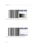
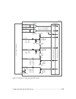
If enabled, the status line replaces the last row of the image with camera status information.
Every parameter is coded into fields of 4 pixels (LSB first) and uses the lower 8 bits of the pixel
value, so that the total size of a parameter field is 32 bit (see Fig. 5.20). The assignment of the
parameters to the fields is listed in Table 5.5.
4
8
1 2
1 6
2 0
P r e a m
b l e
F i e l d 0
0
P i x e l :
1
2
3
5
6
7
9
1 0
1 1
1 3
1 4
1 5
1 7
1 8
1 9
2 1
2 2
2 3
L S B
M
S B
F F
0 0
A A
5 5
F i e l d 1
F i e l d 2
F i e l d 3
F i e l d 4
L S B
L S B
L S B
L S B
L S B
M
S B
M
S B
M
S B
M
S B
M
S B
Figure 5.20: Status line parameters replace the last row of the image
52
Summary of Contents for MV1-R1280-50-G2 Camera Series
Page 6: ...CONTENTS 6...
Page 10: ...2 Introduction 10...
Page 14: ...3 How to get started GigE G2 Figure 3 3 PFInstaller components choice 14...
Page 30: ...4 Product Specification 30...
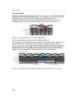
Page 51: ...Figure 5 19 Crosshairs Example with different grey values 5 6 Crosshairs 51...
Page 72: ...6 Hardware Interface 72...
Page 84: ...7 Software 84...
Page 88: ...9 Warranty 88...
Page 90: ...10 References 90...
Page 94: ...B Camera Revisions 94...
Page 95: ...C Document Revision History Revision Date Changes 1 0 April 2015 First version 95...


