


6
Hardware Interface
6.1
GigE Connector
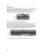
The GigE cameras are interfaced to external components via
•
an Ethernet jack (RJ45) to transmit configuration, image data and trigger.
•
a 12 pin subminiature connector for the power supply, Hirose HR10A-10P-12S (female) .
The connectors are located on the back of the camera. Fig. 6.1 shows the plugs and the status
LED which indicates camera operation.
E
t h e r n e t J a c k ( R J 4 5 )
P o w e r S u p p l y
a n d I / O C o n n e c t o r
S t a t u s L E D
Figure 6.1: Rear view of the GigE camera
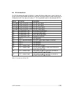
6.2
Power Supply Connector
The camera requires a single voltage input (see Table 4.4). The camera meets all performance
specifications using standard switching power supplies, although well-regulated linear power
supplies provide optimum performance.
It is extremely important that you apply the appropriate voltages to your camera.
Incorrect voltages will damage the camera.
57
Summary of Contents for MV1-R1280-50-G2 Camera Series
Page 6: ...CONTENTS 6...
Page 10: ...2 Introduction 10...
Page 14: ...3 How to get started GigE G2 Figure 3 3 PFInstaller components choice 14...
Page 30: ...4 Product Specification 30...
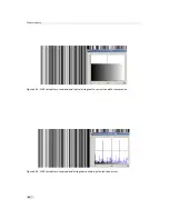
Page 51: ...Figure 5 19 Crosshairs Example with different grey values 5 6 Crosshairs 51...
Page 72: ...6 Hardware Interface 72...
Page 84: ...7 Software 84...
Page 88: ...9 Warranty 88...
Page 90: ...10 References 90...
Page 94: ...B Camera Revisions 94...
Page 95: ...C Document Revision History Revision Date Changes 1 0 April 2015 First version 95...


