


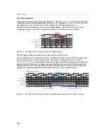


The falling edge of the trigger pulse is delayed by the time t
d
−
iso
−
input
which results from the
signal isolator. This signal is clocked into the FPGA which leads to a jitter of t
jitter
. The pulse is
then delayed by t
trigger
−
delay
by the user defined value which can be configured via camera
software. After the trigger offset time t
trigger
−
offset
the exposure is stopped.
The time from the active trigger edge to the active edge of the next trigger
must not be smaller than the minimal frame time (1 / MaxFrameRate) achievable
with the current camera settings. Violation of this condition can result in corrupt
images or the camera might stop to grab images.
5.2.5
Trigger Delay
The trigger delay is a programmable delay in milliseconds between the incoming trigger edge
and the start of the exposure. This feature may be required to synchronize the external strobe
with the exposure of the camera.
5.2.6
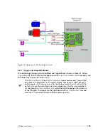
Strobe Output
The strobe output is an isolated output located on the power supply connector that can be
used to trigger a strobe. The strobe output can be used both in free-running and in trigger
mode. Strobe settings:
Strobe_Delay
Programmable delay delay from the active input trigger edge to the rising edge
of the strobe output signal.
Strobe_PulseWidth
Width of the trigger pulse in
µ
s. A setting of 0 turns off the strobe output.
Strobe_Invert
Inverts the strobe output signal. Strobe_Invert=False: strobe signal active high,
Strobe_Invert=True: strobe signal active low.
The strobe output needs a separate power supply. Please see Section 6.5, Fig. 5.3
and Fig. 5.4 for more information.
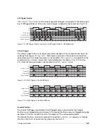
5.2.7
Burst Trigger
The camera includes a burst trigger engine. When enabled, it starts a predefined number of
acquisitions after one single trigger pulse. The time between two acquisitions and the number
of acquisitions can be configured by a user defined value via the camera software. The burst
trigger feature works only in the mode "Camera controlled Exposure Time".
The burst trigger signal can be configured to be active high or active low. When the frequency
of the incoming burst triggers is higher than the duration of the programmed burst sequence,
then some trigger pulses will be missed. A missed burst trigger counter counts these events.
This counter can be read out by the user.
The burst trigger mode is only available when
TriggerMode
=On. Trigger source is determined by
the
TriggerSource
property.
The timing diagram of the burst trigger mode is shown in Fig. 5.7.
.
5.2 Trigger and Strobe
39
Summary of Contents for MV1-R1280-50-G2 Camera Series
Page 6: ...CONTENTS 6...
Page 10: ...2 Introduction 10...
Page 14: ...3 How to get started GigE G2 Figure 3 3 PFInstaller components choice 14...
Page 30: ...4 Product Specification 30...
Page 51: ...Figure 5 19 Crosshairs Example with different grey values 5 6 Crosshairs 51...
Page 72: ...6 Hardware Interface 72...
Page 84: ...7 Software 84...
Page 88: ...9 Warranty 88...
Page 90: ...10 References 90...
Page 94: ...B Camera Revisions 94...
Page 95: ...C Document Revision History Revision Date Changes 1 0 April 2015 First version 95...


