


5 Functionality
5.2.9
A/B Trigger for Incremental Encoder
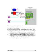
An incremental encoder with A/B outputs can be used to synchronize the camera triggers to
the speed of a conveyor belt. These A/B outputs can be directly connected to the camera and
appropriate triggers are generated inside the camera.
The A/B Trigger feature is is not available on all camera revisions, see Appendix
B for a list of available features.
In this setup, the output A is connected to the camera input ISO_INC0 (see also Section 6.5.4
and Section A.1) and the output B to ISO_INC1.
In the camera default settings the PLC is configured to connect the ISO_INC inputs to the A/B
camera inputs. This setting is listed in Section 7.7.3.
The following parameters control the A/B Trigger feature:
TriggerSource
Set TriggerSource to
ABTrigger
to enable this feature
ABMode
Determines how many triggers should be generated. Available modes: single,
double, quad (see description below)
ABTriggerDirection
Determines in which direction a trigger should be generated:
fwd
: only
forward movement generates a trigger;
bkwd
: only backward movement generates a
trigger;
fwdBkwd
: forward and backward movement generate a trigger.
ABTriggerDeBounce
Suppresses the generation of triggers when the A/B signal bounce.
ABTriggerDeBounce is ignored when
ABTriggerDirection
=
fwdbkwd
.
ABTriggerDivider
Specifies a division factor for the trigger pulses. Value 1 means that all
internal triggers should be applied to the camera, value 2 means that every second
internal trigger is applied to the camera.
EncoderPosition (read only)
Counter (signed integer) that corresponds to the position of
incremental encoder. The counter frequency depends on the ABMode. It counts up/down
pulses independent of the
ABTriggerDirection
. Writing to this property resets the counter
to 0.
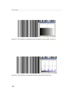
A/B Mode
The property ABMode takes one of the following three values:
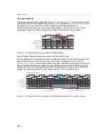
Single
A trigger is generated on every A/B sequence (see Fig. 5.8).
TriggerFwd
is the trigger that
would be applied if
ABTriggerDirection
=
fwd
,
TriggerBkwd
is the trigger that would be
applied if
ABTriggerDirection
=
bkwd
,
TriggerFwdBkwd
is the trigger that would be applied if
ABTriggerDirection
=
fwdBkwd
.
GrayCounter
is the Gray-encoded BA signal that is shown as an
aid to show direction of the A/B signals.
EncoderCounter
is the representation of the
current position of the conveyor belt. This value is available as a camera register.
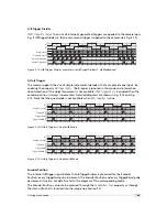
Double
Two triggers are generated on every A/B sequence (see Fig. 5.9).
Quad
Four triggers are generated on every A/B sequence (see Fig. 5.10).
.
42
Summary of Contents for MV1-R1280-50-G2 Camera Series
Page 6: ...CONTENTS 6...
Page 10: ...2 Introduction 10...
Page 14: ...3 How to get started GigE G2 Figure 3 3 PFInstaller components choice 14...
Page 30: ...4 Product Specification 30...
Page 51: ...Figure 5 19 Crosshairs Example with different grey values 5 6 Crosshairs 51...
Page 72: ...6 Hardware Interface 72...
Page 84: ...7 Software 84...
Page 88: ...9 Warranty 88...
Page 90: ...10 References 90...
Page 94: ...B Camera Revisions 94...
Page 95: ...C Document Revision History Revision Date Changes 1 0 April 2015 First version 95...


