


The setting
Counter_ResetCounterMode
=
Continuous
resets the counters on every occurrence of an
active edge of the reset source without the requirement to arm the device first. This setting is
suited if the reset source signal is different than the camera trigger.
The active edge of the reset input can be set by the property
Counter_ResetCounterSourceInvert
.
If set to
True
, then the rising edge is the active edge, else the falling edge.
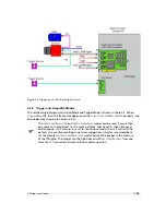
Counter reset by an external signal is important if you would like to synchronize
multiple cameras. One signal is applied to all cameras which resets the coun-
ters simultaneously. The timestamps of all cameras are then theoretically syn-
chronous with each other. In practice every camera runs on its own clock source
which has a precision of +/- 30 ppm and therefore the values of the timestamp
(real time counter) of the cameras may diverge with time. If this is an issue, then
the counters could be reset periodically by the external signal.
The counter reset by an external signal feature might not be available on all
camera revisions, see Appendix B for a list of available features.
5.2.12
Trigger Acquisition
The applied trigger can be enabled or disabled by one or two external signals in the
TriggerAcquisition mode. This mode works with free-running (internal) trigger and external
trigger.
The property
TriggerAcquisition_Enable
enables the TriggerAcquisition mode.
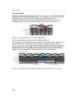
Level Triggered Trigger Acquisition
The Level Triggered mode is enabled by setting
TriggerAcquisition_Mode
to
Level
and
TriggerAcquisition_Enable
=
True
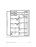
. A signal acts as a trigger enable (see Fig. 5.16). This signal is
selected by
TriggerAcquisition_StartSource
. A high signal level enables triggering of the
camera and a low signal level disables all triggers.
To invert the TriggerAcquisition signal use one of the PLC_Q signal and select
the inverted signal as its source. Table 5.4 shows a setting that uses ISO_IN0 as
trigger enable signal: the inverted signal is used as ISO_IN0 is inverted in the
input logic (see Fig. 7.4).
T
r i g g e r A c q u i s i t i o n _ S t a r t
T r i g g e r I n
A p p l i e d T r i g g e r
I n t e r n a l T r i g g e r E n a b l e
d
i s a b l e d
e n a b l e d
d i s a b l e d
Figure 5.16: Trigger Acquisition Level triggered (TriggerAcquisition_Mode = Level)
5.2 Trigger and Strobe
47
Summary of Contents for MV1-R1280-50-G2 Camera Series
Page 6: ...CONTENTS 6...
Page 10: ...2 Introduction 10...
Page 14: ...3 How to get started GigE G2 Figure 3 3 PFInstaller components choice 14...
Page 30: ...4 Product Specification 30...
Page 51: ...Figure 5 19 Crosshairs Example with different grey values 5 6 Crosshairs 51...
Page 72: ...6 Hardware Interface 72...
Page 84: ...7 Software 84...
Page 88: ...9 Warranty 88...
Page 90: ...10 References 90...
Page 94: ...B Camera Revisions 94...
Page 95: ...C Document Revision History Revision Date Changes 1 0 April 2015 First version 95...


