A B
D
C
F E
#14 End
#12 End
3
H3 & F7 Sandwich Regulator
V-486BP
Installation
1. Remove the valve from the subbase or manifold (if assembled)
by removing and retaining the mounting screws.
2. Convert the valve to external pilot supply per the
Conversion of
Valve to External Pilot Configuration procedure found below.
3. Clean all mating surfaces of valve, subbase or manifold and
sandwich regulator of dust and dirt.
4. Add a drop of low strength thread locking compound to male
threads of male-female tie rods and screw into subbase or
manifold and tighten 9.0 to 11.3 Nm (80 to 100 in-lb).
5. Slide gasket and Sandwich Regulator over male-female tie rods
protruding from top of subbase or manifold and press down on
Sandwich Regulator to seat electrical plug.
6. Place valve on top of Sandwich Regulator lining up all mounting
holes and press down on valve to seat electrical plug.
7. Assemble valve to sandwich regulator with valve mounting screws.
Tighten 9.0 to 11.3 Nm (80 to 100 in-lb).
8. Apply pressure to subbase or manifold and check for audible
leakage at joints.
9. Adjust outlet pressure per
Outlet Pressure Adjustment procedure
at right to verify proper function.
Conversion Of Valve To External Pilot
Supply Configuration
!
CAUTION: H3 & F7 valves equipped with solenoid
operators or remote operated valves with air return must
be converted to external pilot supply in order to insure
proper valve operation.
Sandwich Regulator Model Numbers L95433*** and L95434*** will
provide inlet air from the subbase or manifold to external pilot supply
connection “12” in the valve. Model Numbers L95431*** and L95432***
require that pilot supply air 241 to 1034 kPa (35 to 150 PSIG) be
connected to pilot supply connection “12” in the subbase or manifold.
H3 Valves (Engineering Level ‘A’)
1. #14 End - All Solenoid Operated and Remote Pilot Operated
Valves - Remove nut (A) solenoid coil (B), adapter block screws
(C) and adapter block (D).
2. #12 End - Double Solenoid Operated Valves - Remove
nut (A) solenoid coil (B), adapter block screws (C) and
adapter block (D).
#12 End - Single Solenoid Operated Valves - Remove screws
(E) and air return end cap (F).
3. Position selector seal on valve body as shown below: The
cylindrical projection on the selector seal will block the internal
pilot supply located on the end of the valve body.
4. Reassemble solenoid end cap(s) (D) and air return end cap (F)
(where required). Tighten screws (C & E) 4.5 to 5.6 Nm (40 to 50
in-lb.) torque.
5. Reassemble solenoid coil (B) and nut (A) and tighten 5.1 to 6.2
Nm (45 to 55 in-lb.) torque.
VALVE BODY
SOLENOID ADAPTER
SELECTOR
SEAL
INTERNAL
PILOT
SUPPLY
EXTERNAL
PILOT
SUPPLY
WIRE
PATH
H3 Valves (Engineering Level ‘B’) & F7 Valves
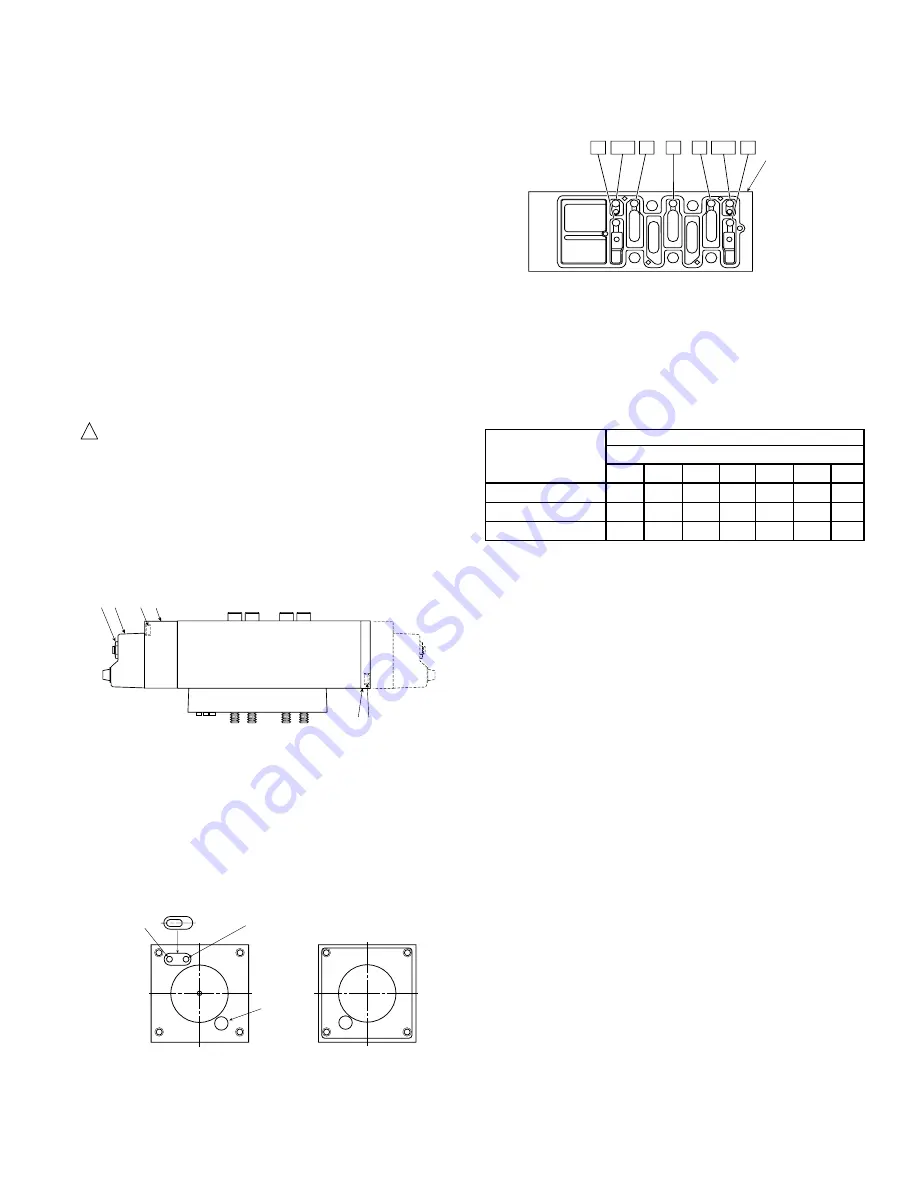
Conversion to external pilot supply is accomplished by inserting small
plugs in the sandwich plate located on the bottom of the valve. These
plugs are located in small holes which are identified as follows:
Place the plugs in the proper holes per the table below as follows:
To remove a plug, insert a narrow tool under the side of the nib and
pry it upward slightly. Then, grasp the projecting nib (long nose pliers
may help) and pull it out. Examine the o-ring to be sure it is not torn or
nicked, and that it has a coating of grease. Install the plug into the
appropriate hole (o-ring end enters first) by pushing it in place until it
comes to a stop and the nib is flush with the surface of the sandwich
block.
Plug Locations
Control Mechanism
Pilot Supply Holes
Operator Types
1
3
5
BP4
BP2
12
14
All Solenoids
X
M
M
X
Single Air Pilot
X
M
M
X
Double Air Pilot
M
M
X
X
Key Code:
X = Pilot hole must be plugged
Blank = Pilot hole must be left open
M = Pilot holes may be molded shut and will not need a plug; however,
some holes may be open and therefore will require a plug. Use a
probe to test if the holes are open - the probe must be able to pass
through the thickness of the sandwich block for the holes to be open.
Valve
Sandwich
Block
3
1
BP2 12
5
BP4
14
Outlet Pressure Adjustment
1. Before turning on the air supply, turn the adjusting knob
counterclockwise until compression is released from the pressure
control spring then turn on air supply. Proceed to adjust the
desired downstream pressure by turning adjusting knob clockwise.
This permits pressure to build up slowly in the downstream line.
2. To decrease regulated pressure setting, always reset from a
pressure lower than the final setting required. Example, lowering
the secondary pressure from 550 kPa (80 PSIG) to 410 kPa (60
PSIG) is best accomplished by dropping the secondary pressure
to 345 kPa (50 PSIG), then adjusting upward to 410 kPa (60
PSIG).
3. When desired secondary pressure setting has been reached,
push the adjusting knob down to lock the adjusting knob.
Regulator Spring Conversion
1. Shut off main and pilot air supplies and depressurize the unit.
2. Disengage the adjusting knob (A) by pulling outward. Turn
adjusting knob counterclockwise until the compression is released
from the pressure control spring (10).
3. Unscrew the collar (B) and remove the bonnet assembly (C).
Remove diaphragm assembly (1) and spring (10).
4. Replace spring (10) with one for new pressure range and
assemble along with diaphragm assembly (1) into bonnet
assembly (C).
5. Assemble bonnet assembly (C) and collar (B) to regulator body.
Tighten collar hand tight plus 1/4 turn.
6. Reapply pressure to unit and check for audible leakage at joints
or out bleed holes.
7. Adjust outlet pressure per
Outlet Pressure Adjustment procedure
above to verify proper function.


