F3 Sandwich Regulators
V-417DP
Installation
Remove pressure and electrical connections before installation.
If valve is not mounted to base skip steps 1 and 2.
1.
Loosen body to base mounting bolts (item #1) using a 3 mm hex
wrench and lift valve body from subbase or manifold. Retain the
gasket (item #4).
2.
Thoroughly clean both valve body and base mounting surfaces of all
foreign residue.
3.
Install the three mounting studs (item #3) contained with the regulator
to the base finger tight. Back studs off so that the flats on the studs
are parallel to side of base.
4.
Place the gasket (item #2) that came with the sandwich regulator into
the grooves on the bottom of the regulator after lightly greasing.
5.
Install the regulator over the studs, engaging the electrical plug carefully
during this process.
6.
Replace the valve on the regulator, making certain first that the interface
gasket (item #4) is in place in its grooves in the sandwich block.
Engage the electrical plug carefully during this process. Tighten the
three main body mounting screws (item #1) from 2.5 to 2.9 N•m
(22 to 26 in-lbs).
7.
Apply main pressure and check for leaks. If any are present, do not
operate the valve - repeat the reassembly process until satisfactory.
NOTE: If both a sandwich flow control and sandwich regulator are to be
installed, the flow control should be installed between the regulator
and the base. Both studs should be installed to base before
installing the flow control.
Remote Operated Only - Connect outlet of pilot regulator to 1/8" port on
end of function block next to regulator. Perform outlet pressure adjustment
on pilot regulator.
Gage Installation
Units are shipped with gage ports plugged, and gages must be ordered
separately.
Standard Gage
Remove 1/8" pipe plug from gage port. Apply pipe sealant (not tape) to
gage male threads, install gage into gage port.
Liquid Filled Gage
The diameter of this type gage requires that method of installation be
alternated between valve stations. The first, third, etc. will be installed
using a nipple and coupling. The second, fourth, etc. are installed with an
elbow, nipple and coupling.
Outlet Pressure Adjustment
1.
To avoid minor readjustment after making a change in pressure setting,
always approach the desired pressure setting from a lower pressure.
2.
Before turning on system air pressure, disengage lock by pulling
adjusting knob outward, and then turn knob counterclockwise until
knob stops.
3.
Turn on system pressure.
4.
Turn adjusting knob clockwise to increase pressure until the desired
pressure setting is reached.
5.
To reduce pressure setting, turn adjusting knob counterclockwise until
pressure decreases to at least 10 PSI lower than desired setting.
Then turn adjusting knob clockwise until the desired pressure setting
is reached.
6.
Push the adjusting knob inward to engage lock.
7.
Resetting may be required to compensate for flow after the valve is
cycling in normal use.
(For remote air operated regulator, follow instructions for the pilot regulator
for setting, using the technique above.)
Regulator Service
Remove pressure and electrical connection before service.
NOTE: Service kit contains components to service both spring and pilot
controlled regulators. When servicing spring controlled units discard
extra piston and lipseal.
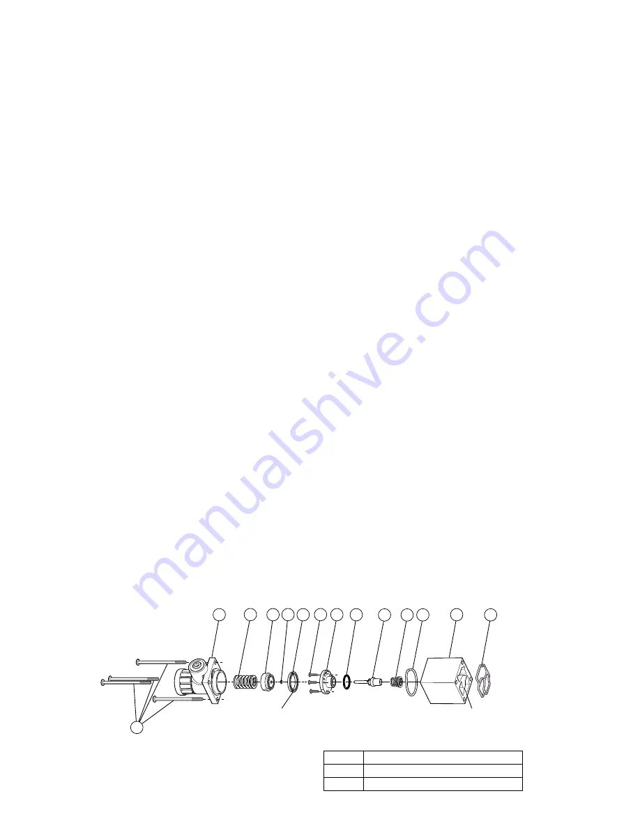
1.
Remove and retain screws (item #15), bonnet assembly (item #14)
and spring (item #13). Remove and discard piston (item #12), piston
lipseal (item #11) and o-ring (item #10).
2.
Remove and retain three seat plate screws (item #22) and seat
plate (item #23). Remove and discard seat plate o-ring (item #24),
bonnet o-ring (item #9), poppet assembly (item #25), and poppet
spring (item #26).
3.
Install new poppet spring (item #26) and poppet assembly (item #25).
4.
Install new seat plate o-ring (item #24) to seat plate (item #23) and
insert seat plate into regulator body (item #8) aligning kidney shape in
seat plate with kidney shape in regulator body. Fasten seat plate with
three screws (item #22), tightening to .35 to .58 N•m (3 to 5 in-lbs).
5.
Liberally grease new lipseal (item #11) and vent o-ring (item #10) and
install on new relieving piston (item #12). Flared edge of lipseal faces
away from the piston.
6.
Place new o-ring (item #9) in groove of regulator body (item #8).
7.
Place spring into bonnet assembly (item #14), followed by piston/
lipseal assembly, with flared edges of seal facing towards body
(item #8).
8.
Assure gasket (item #27) is in regulator block track and install body
to regulator block, followed by bonnet assembly. Install screws
(item #15) and torque to .9 to 1.4 N•m (8 to 12 in-lbs).
9.
Apply main pressure and check for leaks. If any are present, do not
operate the valve - repeat the assembly process until satisfactory.
NOTE: For remote air pilot regulators, follow the above procedures, but
replace both pistons and lipseals. The lipseal for the air operator
has flared edge towards air operator cavity.
Instruction Sheets available:
V-410DP - Valve Installation & Operation
V-411DP - Valve Body Service
V-412DP - Solenoid Service
V-413DP - Manifold Installation
V-414CP - Subbase Installation
V-415CP - Flow Control Installation
V-416CP - Regulator Installation
V-418CP - Manifold With Electrical Interconnect Installation
NOTE: Sandwich regulators can only be used with F3 valves
manufactured after 3/1/97 (date code CB3). These units will have
socket head cap screws for holding the valve body to the base.
Sandwich units will not fit units with button head screws.
Item
Torque
15
.9 - 1.4 N•m (8 - 12 in-lbs)
22
.35 - .58 N•m (3 - 5 in-lbs)
24
23
22
25
15
11
10
12
13
14
27
9
26
8
Note: Gage Port
Towards Top
Note: Flared End
Towards Item 8
Note: Align Pattern
To Regulator Block


