F5 Series Valves - Valve Body Service
V-431BP
7. Remove a new spool assembly (19) from its protective bag and grease
seals and bore. Then insert spool into valve bore, taking care to
install squarely and push slowly to avoid damaging seals or the valve
bore.
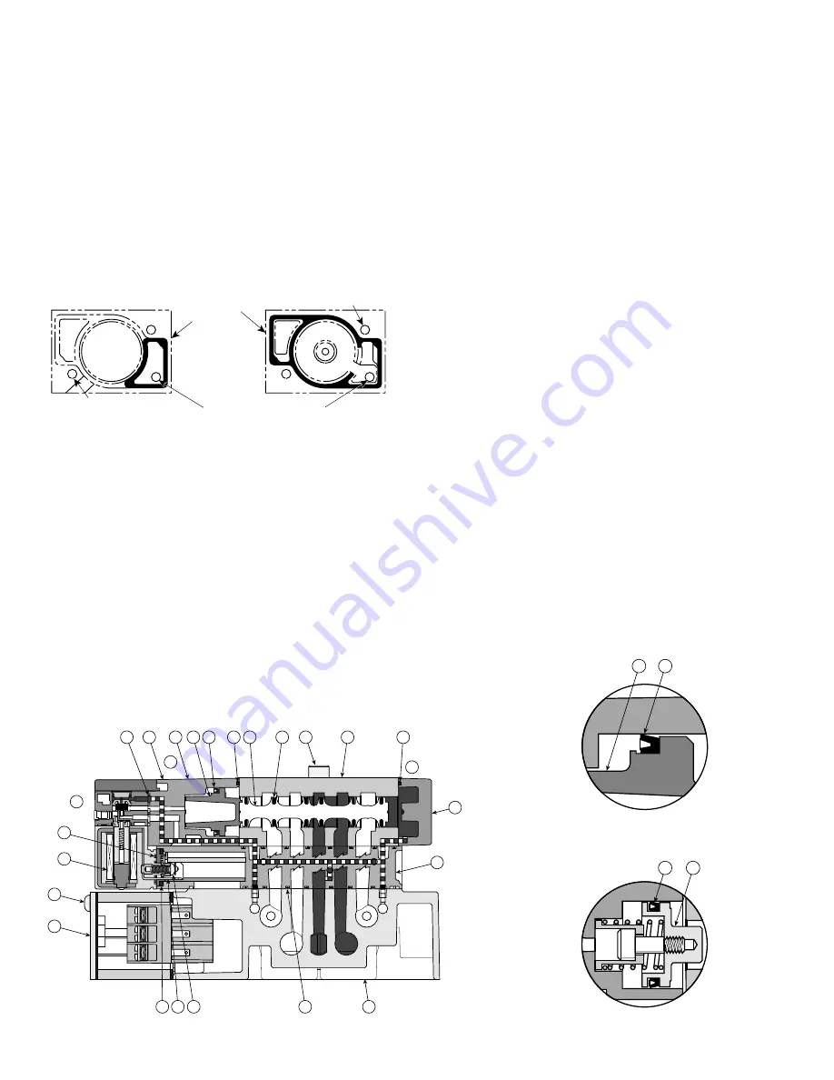
8. Lightly grease new gasket (18) and place into its gasket track on
operator. Depending upon the type of valve being serviced, certain
seals in the service kit may not be used. See Figure 1 for the correct
gasket. Lightly press the gasket into its gasket track, pushing knob
projections into gasket holes.
9. Apply a light film of grease to piston bores and all surfaces of piston
seals. Install seals onto piston with the lips of the seals facing away
from the support flange. See Figure 3.
10. Install the piston (16) & lip seal (17) subassembly into its operator
bore, taking care to assure that the lips of the seal pass smoothly
into the bore.
FIGURE 1: Gaskets for Operators
Pilot Adapter
Return End Cap
NOTE: This gasket is used on
NOTE: This gasket is used on
valves with piston vent and
valves with piston vent and pilot
pilot exhaust out the valve side.
exhaust internally exhausted.
11. Assemble the operator adapter (15) to the valve body (22) using its
two mounting screws (14). Tighten screws from 0.9 to 1.4 N•m
(8 to 12 in-lbs).
NOTE: Be sure to lightly grease the new rectangular gasket (6) and
then place it into the bottom of the rectangular cavity in the
sandwich block.
12. Assemble the solenoid subassembly (4, 9, 10, & 13) onto the
operator adapter (15) using its two mounting screws (11). Tighten
these screws from 0.9 to 1.4 N•m (8 to 12 in-lbs).
13. Assemble the end cap &/or air operator onto the valve body (22)
using two mounting screws (25). Be sure to position end cap so that
its gasket lines up with the air supply hole in the valve body. Tighten
these screws from 0.9 to 1.4 N•m (8 to 12 in-lbs).
14. Check to insure that the gasket (3) on the bottom of the sandwich
block is still properly seated in its gasket track. Then place valve
assembly on top of base (2). Line up electrical plug with socket in
base and gently press down on valve to seat plug properly.
Part Identification List
Item #
Description
1
Sandwich Block
2
Base (subbase or modular manifold)
3
Molded Gasket - sandwich block to base
4
Screw - solenoid coil to operator adapter
5
Electrical Pin
6
Rectangular Gasket - sandwich block to solenoid coil
7
Captive Mounting Screws - end cover to base
8
End Cover
9
Solenoid Coil
10
Gasket - solenoid coil to sandwich adapter
11
Mounting Screw - solenoid coil to operator adapter (not shown)
12
Gasket - operator to operator adapter
13
Sandwich Adapter
14
Screw - operator adapter to valve body (not shown)
15
Operator Adapter
16
Piston (2-Position) or Piston Assembly (3-Position) -
for operator adapter
17
Lip Seal - piston to operator adapter
18
Gasket - operator adapter to valve body
19
Spool Assembly
20
Seals - spool to valve body
21
Captive Mounting Screw - valve body to base
22
Valve Body
23
Screw - end cap to valve body (not shown)
24
Return End Cap
Instruction Sheets Available:
V-430CP - Valve Installation & Operating Instructions
V-432BP - Solenoid Service Instructions
V-433BP - Manifold Installation Instructions
V-434BP - Subbase Installation Instructions
V-435BP - Sandwich Flow Control Installation Instructions
V-436BP - Sandwich Regulator Installation & Operating Instructions
V-437BP - Sandwich Regulator Conversions & Service Instructions
V-438BP - Manifold With Electrical Interconnect Installation
FIGURE 2: Single Solenoid 2-Position Valve Shown
FIGURE 4: Piston Assembly
for 3-Position Valves
FIGURE 3: Enlarged View
of Piston & Lip Seal
16
17
16
17
14
12
COM
BP
1
BP
14
12
1
2
4
5
3
13
12
14
15 16 17
18
18
1
24
9
11
10
8
7
23
19
20
22
2
3
4
5
6
21
Location of Pilot Hole
Mounting Hole
Outline of
End Cap
Mounting Hole
15. Line up the mounting holes and tighten the captive mounting screws
(21). Torque screws at 2.8 to 3.9 N•m (25 to 35 in-lbs) using progressive
steps with a criss-cross pattern.
16. Apply inlet pressure and check for leaks. If any are present, do not
operate the valve - repeat this assembly process until satisfactory.


