background image

  Operation and Simple Running 

8-8


AC10 Inverter 

8.3.4


Setting the frequency with analog terminal and controlling the 

operation with control terminals 

i. 

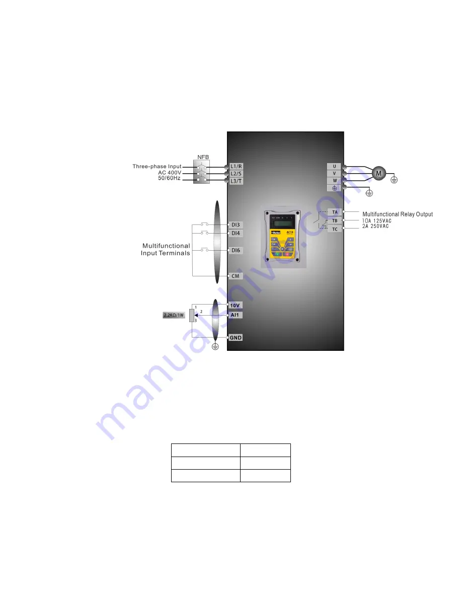
Connect the wires in accordance with 

Figure 8-3

. After having checked the wiring 

successfully, switch on the mains supply, and power on the inverter. Note: 2K

5K 

potentiometer may be used for setting external analog signals. For the cases with 

higher requirements for precision, a precise multiturn potentiometer is 

recommended, and adopt shielded wire for the wire connection, with near end of 

the shielding layer grounded reliably.   


Figure 8-3

    Wiring Diagram 3 


ii. 

Press the “M” key, to enter the programming menu. 

iii. 

Study the parameters of the motor: the operation process is the same as that of 

example 1.  (Refer to 8.3.1 for tuning of the motor). 

iv. 

Set functional parameters of the inverter: 

Function code 

Values 

F203 

F208 


v. 

(5) There is a red two-digit coding switch SW1 near the control terminal block, as 

shown in Figure 4-4. The function of coding switch is to select the voltage signal 

(0

5V/0

10V) or current signal of analog input terminal AI2, current channel is 

default. In actual application, select the analog input channel through F203. Turn 

switches 1 to ON and 2 to ON as illustrated in the figure, and select 0

20mA 

current speed control. Other switches state and mode of control speed are shown 

in table 

Table 8-2

.   

TC-Hydraulik - R

sdorfer Str. 8 - 25746 Heide - Lars Lornsen - T: +49 481 909 - 34 - [email protected] - www.tc-hydraulik.de

Summary of Contents for 10G-42-0065-BF

Page 1: ...pace climate control electromechanical filtration fluid gas handling hydraulics pneumatics process control sealing shielding ENGINEERING YOUR SUCCESS TC Hydraulik Ru sdorfer Str 8 25746 Heide Lars Lornsen T 49 481 909 34 l lornsen tc hydraulik de www tc hydraulik de ...

Page 2: ...TC Hydraulik Ru sdorfer Str 8 25746 Heide Lars Lornsen T 49 481 909 34 l lornsen tc hydraulik de www tc hydraulik de ...

Page 3: ...ensure the accuracy of this document it may be necessary without notice to make amendments or correct omissions Parker SSD Drives cannot accept responsibility for damage injury or expenses resulting therefrom WARRANTY The general terms and conditions of sale of goods and or services of Parker Hannifin Europe Sarl Luxembourg Switzerland Branch Etoy apply to this product unless otherwise agreed The ...

Page 4: ...irements of the application are met The user must analyze all aspects of the application follow applicable industry standards and follow the information concerning the product in the current product catalog and in any other materials provided from Parker or its subsidiaries or authorized distributors To the extent that Parker or its subsidiaries or authorized distributors provide component or syst...

Page 5: ...ber see product label Where installed for your own information Unit used as a refer to Certification for the Inverter Component Relevant Apparatus Unit fitted Wall mounted Enclosure Application Area The equipment described is intended for industrial motor speed control utilising AC induction motors Personnel Installation operation and maintenance of the equipment should be carried out by competent...

Page 6: ...uring ventilation is sufficient provide guarding and or additional safety systems to prevent injury or damage to equipment When replacing a drive in an application and before returning to use it is essential that all user defined parameters for the product s operation are correctly installed The AC10 series is not a safety component or safety related product All control and signal terminals are SE...

Page 7: ...ion 7 1 7 1 Installation 7 1 7 2 Connection 7 1 7 3 Measurement of Main Circuit Voltages Currents and Powers 7 3 7 4 Functions of Control Terminals 7 5 7 5 Wiring for Digital Input Terminals 7 6 7 5 1 Wiring for positive source electrode NPN mode 7 6 7 5 2 Wiring for active source electrode 7 6 7 5 3 Wiring for positive Sink electrode PNP mode 7 6 7 5 4 Wiring for active drain electrode PNP mode 7...

Page 8: ...eration 8 5 8 3 1 Frequency setting start forward running and stop using the keypad panel 8 5 8 3 2 Setting the frequency using the keypad panel and starting forward and reverse running and stopping inverter through control terminals 8 6 8 3 3 Operation process of jogging operation using the keypad panel 8 7 8 3 4 Setting the frequency with analog terminal and controlling the operation with contro...

Page 9: ...n Codes Related to Communication 12 8 12 8 Physical Interface 12 9 12 8 1 Interface instruction 12 9 12 8 2 Structure of Field Bus 12 9 12 9 Grounding and Terminal 12 9 12 9 1 Examples 12 10 Chapter 13 The Default Applications 13 1 13 1 Application 1 Basic Speed Control Default 13 2 13 2 Application 2 Auto Manual Control 13 4 13 3 Application 3 Preset Speeds 13 6 13 4 Application 4 Raise Lower Tri...

Page 10: ...30 15 6 Analog Input and Output F400 F480 15 8 Multi stage Speed Control F500 F580 15 10 Auxiliary Functions F600 F650 15 11 Timing Control and Protection F700 F770 15 12 Motor parameters F800 F830 15 14 PID parameters FA00 FA80 15 15 Torque control parameters FC00 FC40 15 16 TC Hydraulik Ru sdorfer Str 8 25746 Heide Lars Lornsen T 49 481 909 34 l lornsen tc hydraulik de www tc hydraulik de ...

Page 11: ...ferred to as the Product Code Input voltage 1 220 V 240V 1 phase 3 220 V 240V 3 phase 4 400 V 480V 3 phase Industry Rated current A XXXX OOO O Product model Frame Size 1 200 198 412 F Built in filter N without built in filter 16 G 1 1 0025 B F B Built in braking unit 3 242 228 471 2 242 198 418 1 2 Nameplate Example This nameplate shows the product as an AC16 series 2 2 kW inverter with 3 phase in...

Page 12: ...1 4 16G 31 0045 BF 0 75 7 6 4 5 11 5 95 1 4 16G 31 0070 BF 1 5 12 0 7 18 2 96 1 0 16G 31 0100 BF 2 2 14 3 10 21 5 96 0 7 3Ph 400V 16G 41 0020 BF 0 75 4 1 2 6 5 95 1 4 16G 41 0040 BF 1 5 6 9 4 11 0 96 1 4 16G 41 0065 BF 2 2 9 6 6 5 15 0 96 1 0 16G 41 0080 BF 3 7 11 6 8 18 0 96 1 0 16G 41 0090 BF 4 0 13 6 9 21 0 96 0 7 16G 42 0120 BF 5 5 18 8 12 29 0 96 0 47 16G 42 0170 BF 7 5 22 1 17 34 0 96 0 35 1...

Page 13: ...signed Standards for Implementation IEC EN 61800 5 1 2007 Adjustable speed electrical power drive systems safety requirements IEC EN 61800 3 2004 Adjustable speed electrical power drive systems Part 3 EMC product standard including specific test methods IEC 529 1989 EN60529 Degrees of protection provided by enclosure IP code Cable Inverter Remote keypad Waterproof Connector TC Hydraulik Ru sdorfer...

Page 14: ...er or external analog signal 0 5V 0 10V 0 20mA keypad terminal keys external control logic and automatic circulation setting Start Stop Control Terminal control keypad control or communication control Running Command Channels 3 kinds of channels from keypad panel control terminal and MODBUS Frequency Source Frequency sources given digit given analog voltage given analog current and given MODBUS Au...

Page 15: ...f Wait until it is completely discharged Input terminals L1 R L2 S and L3 T are connected to power supply of 400V 230V L1 L2 are connected to 230V while output terminals U V and W are connected to motor Proper grounding should be ensured with grounding resistance not exceeding 4Ω separate grounding is required for motor and inverter Grounding with series connection is forbidden There should be sep...

Page 16: ...5 7 5 11 15 0 4 40 o C 50 o C 50 o C 50 o C 50 o C 50 o C 50 o C 50 o C 50 o C 50 o C 0 75 20 o C 40 o C 50 o C 50 o C 50 o C 50 o C 50 o C 50 o C 50 o C 50 o C 1 5 40 o C 50 o C 50 o C 50 o C 50 o C 50 o C 50 o C 50 o C 2 2 35 oC 40 o C 50 o C 50 o C 50 o C 50 o C 50 o C 50 o C 3 7 25 o C 40 o C 50 o C 50 o C 50 o C 50 o C 50 o C 4 30 o C 40 o C 50 o C 50 o C 50 o C 50 o C 5 5 30 o C 40 o C 50 o ...

Page 17: ...ectrolytic capacitors being damaged The charging time should be longer than 5 hours 4 3 Daily Maintenance Environment temperature humidity dust and vibration would decrease the life of inverter Daily maintenance is necessary to inverters Daily inspecting Inspecting for noise of motor when it is working Inspecting for abnormal vibration of motor when it is working Inspecting for the installing envi...

Page 18: ...ON when voltage is shown Function code Press for function code and for original parameters and keys can be used to select function codes and parameters Press again to confirm In the mode of keypad control and keys can also be used for dynamic speed control key and keys control start and stop Press key to reset inverter in fault status Press Key to set Fwd Rev jogging and select local remote contro...

Page 19: ...ore None 5V Grounding Grounding Signal 1 Signal 2 Signal 3 Signal 4 The default length of remote cable is 1m On the occasion of heavy interference or if remote control cable is longer than 3m add magnetic ring on the cable A B TC Hydraulik Ru sdorfer Str 8 25746 Heide Lars Lornsen T 49 481 909 34 l lornsen tc hydraulik de www tc hydraulik de ...

Page 20: ... parameters that the user can modify to effect different modes of operation The user should be aware that if they set password valid F107 1 the password must be entered first if parameters are to be set after power off or protection is effected i e to call F100 as per the mode in Table 6 2 and enter the correct code User s password is invalid before delivery and user could set corresponding parame...

Page 21: ...00 FC40 11 Subsidiary function F600 F670 6 As parameter setting can take time due to numerous function codes such function is specially designed as Function Code Switchover in a Code Group or between Two Code Groups so that parameters setting becomes convenient and simple Press M key so that the keypad controller will display function code If user presses or key the function code will circularly k...

Page 22: ... Analog line disconnected PID parameters are set wrong ESP During two line three line running mode stop reset key is pressed or external coast stop terminal is closed ESP will be displayed F152 Function code parameter code 10 00 Indicating inverter s current running frequency or rotate speed and parameter setting values etc Flashing in stopping status to display target frequency 0 Holding time whe...

Page 23: ...98 412 171 398 M5 2 242 198 418 215 402 M6 3 242 228 471 210 454 M8 Cover Layout 7 2 Connection Connect R L1 S L2 and T L3 terminals L1 R and L2 S terminals for single phase with power supply to grounding and U V and W terminals to motor Motor shall have to be grounded Otherwise electrified motor causes interference For inverter power lower than 15kW braking cell is also built in If the load inert...

Page 24: ...rounding Terminal Inverter grounding terminal Braking Terminal P B External braking resistor Note no Terminals P or B for inverter without built in braking unit P DC bus line output External connections to optional braking unit P connected to input terminal P or DC of braking unit connected to input terminal of braking unit N or DC Control loop terminals as follows TA TB TC D01 24V CM DI1 DI2 DI3 ...

Page 25: ...upply and output sides include harmonics measurement data depends on the instruments used and circuits measured When instruments for commercial frequency are used for measurement measure the following circuits with the recommended instruments TC Hydraulik Ru sdorfer Str 8 25746 Heide Lars Lornsen T 49 481 909 34 l lornsen tc hydraulik de www tc hydraulik de ...

Page 26: ...e currents Moving iron type AC Ammeter Current should be equal to or less than rated inverter current Difference between the phases is 10 or lower of the rated inverter current Output side power P2 U V W and U V V W W U Electro dynamic type single phase wattmeter P2 W21 W22 2 wattmeter method Output side power factor Pf2 Calculate in similar manner to power supply side power factor 100 2 2 3 2 2 I...

Page 27: ...r F406 The voltage or current signal can be chosen by coding switch See table 7 2 for details the current channel 0 20mA is chosen before delivery AI2 GND Self contained Power supply Ground Ground terminal of external control signal voltage control signal or current source control signal is also the ground of 10V power supply of this inverter 24V Power supply Control power supply Power 24 1 5V gro...

Page 28: ...PN mode or by sink electrode PNP mode If NPN mode is adopted please slide the toggle switch to the end of NPN Wiring for control terminals as follows 7 5 1 Wiring for positive source electrode NPN mode 7 5 2 Wiring for active source electrode If digital input control terminals are connected by sink electrode slide the toggle switch to the end of PNP Wiring for control terminals as follows 7 5 3 Wi...

Page 29: ...connected to 24V 7 5 5 Recommended Wiring Inverter Model LeadSection Area mm 2 Inverter Model LeadSectionArea mm 2 16G 11 0025 BF 1 5 16G 41 0040 BF 2 5 16G 11 0045 BF 2 5 16G 41 0065 BF 2 5 16G 11 0070 BF 2 5 16G 41 0080 BF 2 5 16G 11 0100 BF 4 0 16G 41 0090 BF 2 5 16G 31 0025 BF 1 5 16G 42 0120 BF 4 0 16G 31 0045 BF 2 5 16G 42 0160 BF 4 0 16G 31 0070 BF 2 5 16G 43 0230 BF 6 0 16G 31 0100 BF 4 0 ...

Page 30: ...1 and L2 with power grid for single phase inverters 2 Remote control panels are connected with 8 core telephone wire 485 communication port is on the control terminals 3 485 communication port has built in standard MODBUS communication protocol The terminal sequence is GND 5V A B 4 Inverter has 6 multifunctional input terminals DI1 DI6 5 The contact capacity of inverter is 10A 125VAC 5A 250VAC and...

Page 31: ...by The degree of disturbance is dependent on the drive system immunity of the equipment wiring installation clearance and earthing methods 7 7 1 Noise propagation paths and suppressing methods Noise categories Noise propagation paths TC Hydraulik Ru sdorfer Str 8 25746 Heide Lars Lornsen T 49 481 909 34 l lornsen tc hydraulik de www tc hydraulik de ...

Page 32: ...unded The signal cables should be placed inside a metal tube and should be located as far away as possible from the input output cables of the drive If the signal cables must cross over the power cables they should be placed at right angle to one another 2 Install radio noise filter and linear noise filter ferrite common mode choke at the input and output of the drive to suppress the emission nois...

Page 33: ... not good Note 1 In order to reduce the earthing resistance flat cable should be used because the high frequency impedance of flat cable is smaller than that of round cable with the same CSA 2 If the earthing poles of different equipment in one system are connected together then the leakage current will be a noise source that may disturb the whole system Therefore the drive s earthing pole should ...

Page 34: ... leakage current Leakage Current Between Lines The line leakage current flowing through the distribution capacitors of the drive outside may cause the thermal relay to be falsely activated especially for the drive whose power is lower than 7 5kW When the cable is longer than 50m the ratio of leakage current to motor rated current may be increased and can cause the wrong action of external thermal ...

Page 35: ... mistakes in using power cable filter 1 Too long power cable The filter inside the cabinet should be located near to the input power source The length of the power cables should be as short as possible 2 The input and output cables of the AC supply filter are too close The distance between input and output cables of the filter should be as far apart as possible otherwise the high frequency noise m...

Page 36: ...l command can be selected through the function codes F200 and F201 8 1 5 Operating status of inverter When the inverter is powered on it will have one of four types of operating status Stopped status Programming status Running status Fault alarm status They are described in the following Stopped status If the inverter is re energised if auto startup after being powered on is not set or decelerate ...

Page 37: ... menu Function code group first level menu Function code second level menu Set value of each function code third level menu 8 2 3 Setting the Parameters Setting the parameters correctly is a precondition to give full inverter performance The following is the introduction on how to set the parameters using the keypad panel Operating procedures i Press the M key to enter programming menu ii Press th...

Page 38: ...plate of the motor controlled are as follows numbers of motor poles are 4 rated power is 7 5kW rated voltage is 400V rated current is 15 4A rated frequency is 50 00HZ and rated rotary speed is 1440rpm operation process of measuring the parameters shall be done as described in the following In accordance with the above motor parameters set the values of F801 to F805 correctly set the value of F801 ...

Page 39: ...ng out tuning of the parameters make sure to disconnect the motor from mechanical load to make the motor under entirely no load status It is prohibited to measure the parameters when the motor is at a running status See description of parameter group F800 F830 Setting running control parameters Set the parameters of the inverter and the motor correctly which mainly include target frequency upper a...

Page 40: ...rated power 7 5kW rated voltage 400V rated current 15 4A rated frequency 50 00HZ and rated rotary speed 1440rpm 8 3 1 Frequency setting start forward running and stop using the keypad panel i Connect the wires in accordance with Table 8 1 After having checked the wiring successfully switch on the power to the inverter ii Press the M key to enter the programming menu iii Enter the parameters of the...

Page 41: ...e Values F111 50 00 F200 0 F201 0 F202 0 F203 0 v Press the I key to start the inverter vi During running current frequency of the inverter can be changed by pressing or vii Press the Stop Reset key once the motor will decelerate until it stops running viii Switch off the air switch and power off the inverter 8 3 2 Setting the frequency using the keypad panel and starting forward and reverse runni...

Page 42: ...he motor will decelerate until it stops running ix Switch off the isolator and power off the inverter 8 3 3 Operation process of jogging operation using the keypad panel i Connect the wires in accordance with Figure 8 1 After having checked the wiring successfully switch on the isolator and power on the inverter ii Press the M key to enter the programming menu iii Study the parameters of the motor...

Page 43: ...ogramming menu iii Study the parameters of the motor the operation process is the same as that of example 1 Refer to 8 3 1 for tuning of the motor iv Set functional parameters of the inverter Function code Values F203 1 F208 1 v 5 There is a red two digit coding switch SW1 near the control terminal block as shown in Figure 4 4 The function of coding switch is to select the voltage signal 0 5V 0 10...

Page 44: ...age and current signal the selecting switch is J5 please refer to Figure 8 6 the output relation is shown in Table 8 3 Figure 8 4 Figure 8 5 Figure 8 6 The Setting of Coding Switch and Parameters in the Mode of Analog Speed Control Table 8 2 F203 2 channel AI2 is selected F203 1 channel AI1 is selected SW1 coding switch S1toggle switch Coding Switch 1 Coding Switch 2 Mode of Speed Control OFF OFF ...

Page 45: ...e same function of F137 3 While studying motor parameters motor does not need to be disconnected with load One inverter can only drive one motor Note It is necessary to study the parameters of motor before inverter runs in the sensorless vector control Under sensorless vector control one inverter can only drive one motor and the power of motor should be similar to the power of inverter Otherwise c...

Page 46: ...he decimal and change the second digit after the decimal to 0 The function codes of F813 F814 F815 F816 F817 F818 F819 F820 F821 are used by synchronous motor and asynchronous motor F870 back electromotive force of PMSM unit 0 1mV 1rpm it is back electromotive force value between lines 0 1 999 9 mV rpm it is forbidden to revert to Mfr s value by F160 F871 PMSM D axis inductance unit 0 01 mH 0 01 6...

Page 47: ... time Starting frequency is not limited by the Min frequency set by F112 If the starting frequency set by F109 is lower than Min frequency set by F112 inverter will start according to the setting parameters set by F109 and F110 After inverter starts and runs normally the frequency will be limited by frequency set by F111 and F112 Starting frequency should be lower than Max frequency set by F111 No...

Page 48: ...ng the process of Flycatching base frequency is invalid After Flycatching is finished this function code if valid F119 The reference of setting accel decel time Setting range 0 0 50 00Hz 1 0 max frequency Mfr s value 0 When F119 0 acceleration deceleration time means the time for inverter to accelerate decelerate from 0Hz 50Hz to 50Hz 0Hz When F119 1 acceleration deceleration time means the time f...

Page 49: ...olled by F122 F124 Jogging Frequency Hz Setting range F112 F111 Mfr s value 5 00Hz F125 Jogging Acceleration Time S Setting range 0 1 3000 Mfr s value subject to inverter model F126 Jogging Deceleration Time S There are two types of jogging keypad jogging and terminal jogging Keypad jogging is valid only under stopped status Carry out jogging operation through the keypad under stopped status a Whe...

Page 50: ...rrent output frequency function code 1 Output rotary speed 2 Output current 4 Output voltage 8 PN voltage 16 PID feedback value 32 Temperature 64 Reserved 128 Linear speed 256 PID given value 512 Reserved 1024 Reserved 2048 Output power 4096 Output torque Mfr s value 0 1 2 4 8 15 Selection of one value from 1 2 4 8 16 32 64 and 128 shows that only one specific display item is selected Should multi...

Page 51: ...0 200 0 Mfr s value 1 00 F134 Transmission wheel radius 0 001 1 000 m Mfr s value 0 001 Calculation of rotary speed and linear speed For example If inverter s max frequency F111 50 00Hz numbers of motor poles F804 4 drive ratio F133 1 00 transmission shaft radius R 0 05m then Transmission shaft perimeter 2πR 2 3 14 0 05 0 314 meter Transmission shaft rotary speed 60 operation frequency numbers of ...

Page 52: ...ance Please refer to the chapter Operation process of measuring motor parameters F140 User defined frequency point F1 Setting range 0 F142 Mfr s value 1 00 F141 User defined voltage point V1 Setting range 0 100 Mfr s value 4 F142 User defined frequency point F2 Setting range F140 F144 Mfr s value 5 00 F143 User defined voltage point V2 Setting range 0 100 Mfr s value 13 F144 User defined frequency...

Page 53: ...mechanical system decrease leakage current of wire to earth and the interference of inverter When carrier wave frequency is low although carrier wave noise from motor will increase the current leaked to the earth will decrease The wastage of motor and the temperature of motor will increase but the temperature of inverter will decrease When carrier wave frequency is high the situations are opposite...

Page 54: ... raise the frequency from 15Hz to 20Hz User can also set F155 5Hz and F160 0 0 means forward 1 means reverse In this way inverter can be run to 20Hz directly F159 Random carrier wave selection Setting range 0 Invalid 1 Valid Mfr s value 1 When F159 0 inverter will modulate as per the carrier wave set by F153 When F159 1 inverter will operate in mode of random carrier wave modulating Note when rand...

Page 55: ...ning locking 2 Terminal setting 3 Keypad Mfr s value 0 The running direction is controlled by this function code together with other speed control mode which can set the running direction of inverter When auto circulation speed is selected by F500 2 this function code is not valid When speed control mode without controlling direction is selected the running direction of inverter is controlled by t...

Page 56: ...s that the target frequency will restore to the value of F113 after stop no matter the state of F220 9 PID adjusting When PID adjusting is selected the running frequency of inverter is the value of frequency adjusted by PID Please refer to instructions of PID parameters for PID given resource PID given numbers feedback source and so on 10 MODBUS The main frequency is given by MODBUS communication ...

Page 57: ... F204 1 When F207 5 X Y the frequency is set by subtracting secondary frequency source from main frequency source If the frequency is set by main frequency or secondary frequency PID speed control cannot be selected Notes When F203 4 and F204 1 the difference between F207 1 and F207 4 is that when F207 1 frequency source selecting is the addition of stage speed and analog when F207 4 frequency sou...

Page 58: ...rol set F208 to 0 If F208 0 when selecting two line type or three line type F200 F201 and F202 are invalid FWD REV and X are three terminals designated in programming DI1 DI5 1 Two line operation mode 1 this mode is the most popularly used two line mode The running direction of mode is controlled by FWD REV terminals For example FWD terminal open stop closed forward running REV terminal open stop ...

Page 59: ...led by FWD terminal The running direction is controlled by REV terminal and stopping command enable by opening X terminal SB1 Running button SB2 Stop button K1 direction switch Open stands for forward running close stands for reverse running 5 Start stop controlled by direction pulse FWD terminal impulse signal forward stop REV terminal impulse signal reverse stop CM terminal common port Note when...

Page 60: ... is valid When F212 0 after inverter is stopped reset and repowered on the running direction is not memorized When F212 1 after inverter is stopped reset and repowered on if inverter starts running but no direction signal inverter will run according the memory direction F213 Auto starting after repowered on Setting range 0 invalid 1 valid Mfr s value 0 F214 Auto starting after reset Setting range ...

Page 61: ... in case of repeated faults If starting times are more than the setting value of this function code inverter will not reset or start automatically after fault Inverter will run after running command is given to inverter manually F217 sets delay time for fault reset The range is from 0 0 to 10 0S which is time interval from fault to resetting F220 Frequency memory after power down Setting range 0 i...

Page 62: ...to combine with other modes If the combination includes the mode of automatic cycle speed control only main speed control mode will be valid 224 1 when target frequency is lower than Min frequency inverter will run at Min frequency F228 can be set to Mfr s value by F160 1 F224 when target frequency is lower than Min frequency Setting range 0 stop 1 run at min frequency Mfr s value 1 F228 Applicati...

Page 63: ... braking Indicating that inverter is in the status of DC braking and ON signal is output 7 Acceleration deceleration time switchover Indicating that inverter is in the status of acceleration deceleration time switchover 8 Reserved 9 Reserved 10 Inverter overload pre alarm Stall Warning After inverter overloads ON signal is output after the half time of protection timed ON signal stops outputting a...

Page 64: ...ting value and after the setting time of F755 ON signal is output refer to F754 and F755 21 Output controlled by PC PLC 1 means output is valid 0 means output is invalid 22 Reserved 23 TA TC Output controlled by PC PLC 24 Watchdog token output The token output is valid when inverter trips into Err6 25 29 Reserved 40 Switchover of high frequency performance When this function is valid inverter will...

Page 65: ...inverter current is higher than F310 DO1 outputs ON signal When inverter current is lower than 100 100 10 90A DO1 outputs OFF signal F312 Frequency arrival threshold At Speed Setting range 0 00 5 00Hz Mfr s value 0 00 When F300 15 or F301 15 threshold range is set by F312 For example when F301 15 target frequency is 20HZ and F312 2 the running frequency reaches 18Hz 20 2 ON signal is output by DO1...

Page 66: ... Manual running 57 Auto running 58 Direction Mfr s value 11 F317 DI2 terminal function setting Mfr s value 9 F318 DI3 terminal function setting Mfr s value 15 F319 DI4 terminal function setting Mfr s value 16 F320 DI5 terminal function setting Mfr s value 7 This parameter is used for setting the corresponding function for multifunctional digital input terminal Both free stop and external coast sto...

Page 67: ...e is set by F211 14 DOWN frequency decreasing terminal 15 FWD terminal When start stop command is given by terminal or terminals combination running direction of inverter is controlled by external terminals 16 REV terminal 17 Three line input X terminal FWD REV CM terminals realize three line control See F208 for details 18 Acceleration deceleration time switchover 1 Refer to table 9 4 21 Frequenc...

Page 68: ...o run 56 Manual run In the application 2 if the function is valid inverter will run manually 57 Auto running In the application 2 if the function is valid inverter will run automatically 58 Direction In the application 1 and 2 the function is used to give direction When the function is valid inverter will run reverse Or else inverter will run forward Figure 9 6 PTC Heat Protection When the coding ...

Page 69: ...speed 10 F513 F528 F543 F574 1 0 1 0 Multi stage speed 11 F514 F529 F544 F575 1 0 1 1 Multi stage speed 12 F515 F530 F545 F576 1 1 0 0 Multi stage speed 13 F516 F531 F546 F577 1 1 0 1 Multi stage speed 14 F517 F532 F547 F578 1 1 1 0 Multi stage speed 15 F518 F533 F548 F579 1 1 1 1 None None Note 1 K4 is multi stage speed terminal 4 K3 is multi stage speed terminal 3 K2 is multi stage speed termina...

Page 70: ...nds for the status of DI1 DI6 terminals In four line LCD please set F645 22 at first after pressing FUN key the displayed interface can be switched into eight 0 They are used to display the DI terminal status If DIX is connected to CM and 0 changes to 1 it means the DIX terminal is valid 9 3 3 Analog input monitoring T The value of analog is displayed by 0 4095 F335 Relay output simulation Setting...

Page 71: ...by F400 and F402 For example when F400 1 F402 8 if analog input voltage is lower than 1V system judges it as 0 If input voltage is higher than 8V system judges it as 10V suppose analog channel selects 0 10V If Max frequency F111 is set to 50Hz the output frequency corresponding to 1 8V is 0 50Hz The filtering time constant is set by F405 The greater the filtering time constant is the more stable f...

Page 72: ... 1 00 F408 Upper limit of AI2 channel input V Setting range F406 10 00 Mfr s value 10 00 F409 Corresponding setting for upper limit of AI2 input Setting range Max 1 00 F407 2 00 Mfr s value 2 00 F410 AI2 channel proportional gain K2 Setting range 0 0 10 0 Mfr s value 1 0 F411 AI2 filtering time constant S Setting range 0 1 50 0 Mfr s value 0 10 The function of AI2 is the same with AI1 F418 AI1 cha...

Page 73: ...utput frequency is set by F424 and F425 For example when F423 0 F424 10 and F425 120 analog channel AO1 outputs 0 5V and the output frequency is 10 120Hz AO1 output compensation is set by F426 Analog excursion can be compensated by setting F426 F431 AO1 analog output signal selecting Setting range 0 Running frequency 1 Output current 2 Output voltage 3 Analog AI1 4 Analog AI2 5 Input pulse 6 Outpu...

Page 74: ... Mfr s value 8 00 F467 AI1 insertion point A3 setting value Setting range F465 F403 Mfr s value 1 80 F468 AI2 insertion point B1 voltage value V Setting range F406 F470 Mfr s value 2 00 F469 AI2 insertion point B1 setting value Setting range F407 F471 Mfr s value 1 20 F470 AI2 insertion point B2 voltage value V Setting range F468 F472 Mfr s value 5 00 F471 AI2 insertion point B2 setting value Sett...

Page 75: ... 3 stage speed control The priority in turn is stage 1 speed stage 2 speed and stage 3 speed It can be combined with analog speed control If F207 4 3 stage speed control is prior to analog speed control 4 1 15 stage speed control It can be combined with analog speed control If F207 4 15 stage speed control is prior to analog speed control 4 2 Max 8 stage speed auto circulating Adjusting the runnin...

Page 76: ...quency setting for stage 4 speed Hz Mfr s value 20 00 F508 Frequency setting for stage 5 speed Hz Mfr s value 25 00 F509 Frequency setting for stage 6 speed Hz Mfr s value 30 00 F510 Frequency setting for stage 7 speed Hz Mfr s value 35 00 F511 Frequency setting for stage 8 speed Hz Mfr s value 40 00 F512 Frequency setting for stage 9 speed Hz Mfr s value 5 00 F513 Frequency setting for stage 10 s...

Page 77: ...tial frequency In some applications such as fan motor is running at a low speed or in a reverse status if inverter starts immediately OC malfunction will occur Adopting braking before starting will ensure that the fan stays in a static state before starting to avoid this malfunction Figure 9 11 DC Braking During braking before starting if stop signal is given inverter will stop by deceleration tim...

Page 78: ...will change accel decel time Please use this function properly Initial value of stalling current adjusting is set by F608 when the present current is higher than rated current F608 stalling current adjusting function is valid During the process of deceleration stalling current function is invalid During the process of acceleration if output current is higher than initial value of stalling current ...

Page 79: ...uto starting when running command valid but direction signal lost and auto starting when running command invalid When F613 2 the function is valid at the first time after inverter is repower on Note When F106 0 Flycatching function is invalid F614 Flycatching mode Setting range 0 Flycatching from frequency memory 1 Flycatching from max frequency 2 Flycatching from frequency memory and direction me...

Page 80: ...C adjustment is used to control voltage steady by adjusting output frequency or reducing braking torque If the DC bus voltage is higher than the setting value of F632 VDC adjustor will automatically adjust the bus voltage same as the value of F632 F650 High frequency performance Setting range 0 Invalid 1 Terminal enabled 2 Enabled mode 1 3 Enabled mode 2 Mfr s value 2 F651 Switchover frequency 1 S...

Page 81: ...l run when inverter begins running When inverter stops fan won t stop until the heat sink temperature is lower than setting temperature F704 Inverter Overloading pre alarm Coefficient Setting range 50 100 Mfr s value 80 F705 Motor Overloading pre alarm Coefficient Setting range 50 100 Mfr s value 80 F706 Inverter Overloading Coefficient Setting range 120 190 Mfr s value 150 F707 Motor Overloading ...

Page 82: ...to Figure 9 21 F707 100 Figure 9 13 Motor overload protection value F708 Record of The Latest Malfunction Type Setting range 2 over current OC 3 over voltage OE 4 input phase loss PF1 F709 Record of Malfunction Type for Last but One 200 70 100 Motor overload coefficient Current 10 160 1 140 110 Time minutes 140 180 5Hz 5 10Hz 1 Current 10Hz 200 10 160 120 Time minutes TC Hydraulik Ru sdorfer Str 8...

Page 83: ...quency of The Latest Malfunction F712 Fault Current of The Latest Malfunction F713 Fault PN Voltage of The Latest Malfunction F714 Fault Frequency of Last Malfunction but One F715 Fault Current of Last Malfunction but One F716 Fault PN Voltage of Last Malfunction but One F717 Fault Frequency of Last Malfunction but Two F718 Fault Current of Last Malfunction but Two F719 Fault PN Voltage of Last Ma...

Page 84: ...ng time constant is and the better for the filtering effect F737 Over current 1 protection Setting range 0 Invalid 1 Valid Mfr s value 1 F738 Over current 1 protection coefficient Setting range 0 50 3 00 Mfr s value 2 50 F739 Over current 1 protection record F738 OC 1 value inverter rated current In running status F738 is not allowed to modify When over current occurs OC1 is displayed F741 Analog ...

Page 85: ... F747 1 the temperature of the heatsink reaches 86 inverter carrier frequency will adjust automatically to decrease the temperature of inverter This function can avoid overheat malfunction When F159 1 random carrier frequency is selected F747 is invalid F754 Zero current threshold Setting range 0 200 Mfr s value 5 F755 Duration time of zero current S Setting range 0 60 Mfr s value 0 5 When the out...

Page 86: ... the load Set F801 805 and F810 correctly prior to running testing Operation process of rotating tuning Press the I key on the keypad to display TEST and it will tune the motor s parameter in two stages After that the motor will accelerate according to acceleration time set at F114 and maintain it for a certain period The motor will then decelerate to 0 according to the time set at F115 After auto...

Page 87: ...ge automatically F802 and F805 can be set manually F806 Stator resistance Setting range 0 001 65 00Ω F807 Rotor resistance Setting range 0 001 65 00Ω F808 Leakage inductance Setting range 0 01 650 0mH F809 Mutual inductance Setting range 0 1 6500mH The set values of F806 F809 will be updated automatically after normal completion of parameter tuning of the motor The inverter will restore the parame...

Page 88: ...e to oscillation Recommended adjusting procedures Make fine adjustment of the value starting from the manufacturer value if the manufacturer setting value cannot meet the needs of practical application Be cautious that amplitude of adjustment each time should not be too large In the event of weak loading capacity or slow rising of rotary speed increase the value of KP first under the precondition ...

Page 89: ...le close loop system with convenient operation FA01 PID adjusting target given source Setting range 0 FA04 1 AI1 2 AI2 Mfr s value 0 When FA01 0 PID reference target is given by FA04 or MODBUS When FA01 1 PID reference target is given by external analog AI1 When FA01 2 PID reference target is given by external analog AI2 FA02 PID feedback signal given source Setting range 1 AI1 2 AI2 Mfr s value 1...

Page 90: ...ge 0 0 3000 Mfr s value 3 0 FA18 Whether PID adjusting target is changed 0 Invalid 1 Valid Mfr s value 1 When FA18 0 PID adjusting target cannot be changed FA19 Proportion Gain P Setting range 0 00 10 00 Mfr s value 0 3 FA20 Integration time I S Setting range 0 1 100 0 Mfr s value 0 3 FA21 Differential time D S Setting range 0 0 10 0 Mfr s value 0 0 FA22 PID sampling period S Setting range 0 1 10 ...

Page 91: ... protection occur inverter will reset automatically and start running and inverter will run at the frequency of FA60 or target frequency until inverter is broken Emergency fire mode 1 when the terminal is valid inverter will run at target frequency Emergency fire mode 2 when the terminal is valid inverter will run at the frequency of FA60 FA60 Running frequency of emergency fire Setting range F112...

Page 92: ...alog input AI2 0 FC07 Torque reference coefficient analogue input 0 3 000 3 000 FC09 Torque reference command value 0 300 0 100 0 FC07 when input given torque reaches max value FC07 is the ratio of inverter output torque and motor rated torque For example if FC06 1 F402 10 00 FC07 3 00 when AI1 channel output 10V the output torque of inverter is 3 times of motor rated torque FC14 Offset torque ref...

Page 93: ...en FC30 1 Analog input AI1 2 Analog input AI2 4 Pulse input channel FI 5 Reserved 0 FC29 Driving torque limit coefficient 0 3 000 3 000 FC30 Driving torque limit 0 300 0 200 0 FC31 Braking torque limit channel 0 Digital given FC35 1 Analog input AI1 2 Analog input AI2 4 Pulse input channel FI 5 Reserved 0 FC34 Braking torque limit coefficient 0 3 000 3 000 FC35 Braking torque limit 0 300 0 200 00 ...

Page 94: ...wer check if power input is normal check if parameter setting is correct PF0 Output Phase Loss Motor is broken Motor wire is loose Inverter is broken check if wire of motor is loose check if motor is broken L U Under Voltage Protection Input voltage on the low side check if supply voltage is normal check if parameter setting is correct O H Heatsink Overheat environment temperature too high Heatsin...

Page 95: ...meters setting correct Correct wiring Set the parameters correctly Motor Turning but Speed Change not Possible Wiring correct for lines with given frequency Correct setting of running mode Too big with load Correct wiring To correct setting Reduce load Motor Speed Too High or Too Low Motor s rated value correct Drive ratio correct Inverter parameters are set in corrected Check if inverter output v...

Page 96: ...16G 31 0100 BF 2 2 16G 41 0020 BF 0 75 80W 200Ω 16G 41 0040 BF 1 5 80W 150Ω 16G 41 0065 BF 2 2 150W 150Ω 16G 41 0080 BF 3 7 16G 41 0090 BF 4 0 16G 42 0120 BF 5 5 250W 120Ω 16G 42 0160 BF 7 5 500W 120Ω 16G 43 0230 BF 11 1kW 90Ω 16G 43 0320 BF 15 1 5kW 80Ω Note in the occasion of large inertia load if the braking resistor heat is excessive use a larger power of resistor than the recommended resistor...

Page 97: ... 1 Data N High order byte of LRC Low or der byte of LRC Return 0X0D Line Feed 0X0A RTU mode Start Address Function Data CRC check End T1 T2 T3 T4 Inverter Address Function Code N data Low order byte of CRC High order byte of CRC T1 T2 T3 T4 12 2 2 ASCII Mode In ASCII mode one Byte hexadecimal format is expressed by two ASCII characters For example 31H hexadecimal data includes two ASCII characters...

Page 98: ...s complement 12 5 2 RTU Mode Cyclical Redundancy Check CRC The CRC field is two bytes containing a 16 bit binary value The CRC is started by first preloading a 16 bit register to all 1 s Then a process begins of applying successive 8 bit bytes of the message to the current contents of the register Only the eight bits of data in each character are used for generating the CRC Start and stop bits and...

Page 99: ...es parameters address i Use the function code as parameter address General Series High order byte 01 0A hexadecimal Low order byte 00 50 max range hexadecimal Function code range of each partition is not the same For the specific range refer to manual For example parameter address of F114 is 010E hexadecimal parameter address of F201 is 0201 hexadecimal Note in this situation it allows to read six...

Page 100: ... loss PF1 0X07 Frequency Over load OL1 0X08 Under voltage LU 0X09 Overheat OH 0X0A Motor overload OL2 0X0B Interference Err 0X0C LL 0X0D External Malfunction ESP 0X0E Err1 0X0F Err2 0X10 Err3 0X11 Err4 0X12 OC1 0X13 PF0 0X14 Analog disconnected protection AErr 0X15 EP3 0X16 Under load protection EP 0X17 PP 0X18 Pressure control protection nP 0X19 PID parameters are set incorrectly Err5 0X22 PMSM d...

Page 101: ...e 0000 no function 0001 stage speed 1 0010 stage speed 2 0011 stage speed 3 0100 stage speed 4 0101 stage speed 5 0110 stage speed 6 0111 stage speed 7 1000 stage speed 8 1001 stage speed 9 1010 stage speed 10 1011 stage speed 11 1100 stage speed 12 1101 stage speed 13 1110 stage speed 14 1111 stage speed 15 Monitoring in which stage speed inverter is 1014 External counting value Monitoring extern...

Page 102: ...ock remote control any remote control commands are no valid before unlocking 0003 RAM and eeprom are permitted to be written 0004 Only RAM is permitted to be written eeprom is prohibited being written 12 6 3 Control commands Writing parameter address Function Remarks 2002 AO1output percent is set by PC PLC Setting range 0 1000 F431 7 AO1 token output analog is controlled by PC PLC 2003 Reserved 20...

Page 103: ...requency actual value X 10 Medium Frequency Series Parameter Values of Time actual value X 10 Parameter Values of Current actual value X 10 Parameter Values of Voltage actual value X 1 Parameter Values of Power actual value X 100 Parameter Values of Drive Ratio actual value X 100 Parameter Values of Version No actual value X 100 Instruction Parameter value is the value sent in the data package Act...

Page 104: ...y source X 0 Digital setting memory 1 External analog AI1 2 External analog AI2 3 Pulse input given 4 Stage speed control 0 F900 Inverter Address 1 255 single inverter address 0 Broadcast address 1 F901 Modbus Mode Selection 1 ASCII mode 2 RTU mode 1 F903 Parity Check 0 Invalid 1 Odd 2 Even 0 F904 Baud Rate bps 0 1200 1 2400 2 4800 3 9600 4 19200 3 Set functions code related to communication conso...

Page 105: ...ain elements as well 12 9 Grounding and Terminal Terminal resistance of 120 Ω will be adopted for terminal of RS485 network to diminish the reflection of signals Terminal resistance shall not be used for intermediate network No direct grounding shall be allowed for any point of RS485 network All the equipment in the network shall be well grounded via their own grounding terminal Please note that g...

Page 106: ...Read output frequency output voltage output current and current rotate speed from N0 2 inverter Host Query Address Function First Register Address Hi First Register Address Lo Register count Hi Register count L0 CRC Lo CRC Hi 02 03 10 00 00 04 40 FA Communication Parameters Address 1000H Slave Response Address Function Byte Count Data Hi Data Lo Data Hi Data Lo Data Hi Data Lo Data Hi Data Lo Crc ...

Page 107: ...lue of F113 F114 from NO 2 inverter Host Query Address Function Register Address Hi Register Address Lo Register Count Hi Register Count L0 CRC Lo CRC Hi 02 03 01 0D 00 02 54 07 Communication Parameter Address F10DH Numbers of Read Registers Slave Normal Response Address Function Byte count The first parameters status Hi The first parameters status Lo The second parameters status Hi The second par...

Page 108: ...n 3 supplies speed control using preset speeds Application 4 supplies speed control using terminal Application 5 supplies speed control using PID Control wiring of application Normally open push button 2 position switch Normally open contact relay The default application is 0 this gives complete access to all operating lists in this manual to select one of the default control application macros se...

Page 109: ...Square compensation F137 V F compensation 50 60 Hz 0 Running frequency Running current Analog input AI1 Running voltage Output torque PC PLC control Target frequency 1 2 3 4 5 6 7 F431 Analog output select Frequency H z 0 Analog input V 4 Motor current A 2 DI AGNOSTI C S F131 I FEBK Coast stop 1 2 3 5 6 4 7 8 9 10 11 12 13 14 15 16 17 18 TA TB TC 1 DO 24V CM DI1 DI2 DI3 DI4 DI5 10V 1 AI 2 AI GND 1...

Page 110: ...stop 1 2 3 5 6 4 7 8 9 10 11 12 13 14 15 16 17 18 TA TB TC 1 DO 24V CM DI1 DI2 DI3 DI4 DI5 10V 1 AI 2 AI GND 1 AO A B REF Stop Jog Direction Run Speed trim not used not used Analog output F431 0 running frequency is output GND Speed trim AI2 input4 20 mA Speed setpointAI1 input0 10V 10V Coast stop Stop Jog The jogging direction is controlled by DI2 Direction When the function is valid inverter run...

Page 111: ...6 17 18 TA TB TC 1 DO 24V CM DI1 DI2 DI3 DI4 DI5 10V 1 AI 2 AI GND 1 AO REF Direction Auto manual select Manual run Auto run Manual auto select F803 Motor rated current F112 Min frequency F114 Acc l e ti me F810 Motor rated frequency Over latent frequency 2 A B AUTOMATI C Pu mp Aut o Manual Sel ect or Aut o Spe e d Refere nce Level Li m it Switch Level Se ns or LEVEL CONTROL Application 2 Auto Man...

Page 112: ...18 TA TB TC 1 DO 24V CM DI1 DI2 DI3 DI4 DI5 10V 1 AI 2 AI GND 1 AO A B REF Direction Auto manual select Manual run Auto run Auto setpoint not used not used Analog output F431 0 running frequency is output GND Auto setpointAI 2input4 20 mA Manual setpoint AI1 input0 10V 10V Coast stop Direction Auto manual select Manual run Auto run CM 24V not used Relay output The function is valid inverter runs r...

Page 113: ...nt F112 Min frequency F115 Decel ti me Application 3 Current li mit F803 Rated current I FEBK V F SHAPING F115 Decel ti me Speed demand F114 Acc l e ti me FWD REV Max Min frequency F810 Motor rated frequency F138 Linear compensation 1 Square compensation 0 linear compensation F137 V F compensation F505 Present 2 F506 Present 3 F506 Present 4 F508 Present 5 F509 Present 6 F510 Present 7 F511 Presen...

Page 114: ...V 3 0V 24V 24V 4 24V 0V 0V 5 24V 0V 24V 6 24V 24V 0V 7 24V 24V 24V 8 Coast stop 1 2 3 5 6 4 7 8 9 10 11 12 13 14 15 16 17 18 TA TB TC 1 DO 24V CM DI1 DI2 DI3 DI4 DI5 10V 1 AI 2 AI GND 1 AO A B REF Run forward Speed trim not used not used Analog output F431 0 running frequency is output GND Speed trim AI2 input 4 20 mA Speed setpoint AI 1input 0 10V 10V Coast stop Preset select1 Auto run CM 24V not...

Page 115: ...124 Jog setpoint F209 Stop mode F137 Torque compensation F138 Linear compensation F108 Password F803 Motor rated current F112 Min frequency F115 Decel ti me Current li mit F803 Rated current I FEBK control V F SHAPING F810 Rated frequency F300 Relay None Fault protection Over latent frequency 1 Over latent frequency 2 At speed F111 Max frequency F112 Min frequency F113 Target frequency Sequencing ...

Page 116: ...8 1 F316 15 F317 13 F318 14 F319 54 Coast stop 1 2 3 5 6 4 7 8 9 10 11 12 13 14 15 16 17 18 TA TB TC 1 DO 24V CM DI1 DI2 DI3 DI4 DI5 10V 1 AI 2 AI GND 1 AO A B Run forward not used not used Analog output F431 0 running frequency is output GND 10V Coast stop Reset Run forward CM 24V not used Relay output F300 1 inverter outputs fault signal Lower input Raise input Reset Lower input Raise input not ...

Page 117: ...P TA TC Given source Current limit PWM control CT VT V F F V V F F138 Linear compensation F803 Rated current 0 linear compensation F137 V F compensation 50 60 Hz F810 Rated frequency FWD REV F114 Accel time RAMP F115 Decle time F112 Min frequency I FEBK Spe ed Set point Pr es s ur e or Volu me Fe edback Tr ans ducer Standard parameters F228 Application F111 Max frequency F114 Acc l e ti me F810 Mo...

Page 118: ...317 58 F318 52 F319 2 F320 8 F431 0 FA01 1 FA02 2 1 2 3 5 6 4 7 8 9 10 11 12 13 14 15 16 17 18 TA TB TC 1 DO 24V CM DI1 DI2 DI3 DI4 DI5 10V 1 AI 2 AI GND 1 AO A B REF Stop Jog Direction Run Feedback source not used not used Analog output F431 0 running frequency is output GND Feedback source AI 2input4 20 mA Speed setpoint AI1 input0 10V 10V Coast stop Stop Jog The jogging direction is controlled ...

Page 119: ...idential commercial and light industrial environments EN 61000 6 4 2007 Electromagnetic compatibility EMC Part 6 4 General standards Emission standard for residential commercial and light industrial environments RESTRICTION EVALUATION AUTHORISATION AND RESTRICTION OF CHEMICALS REACH The Regulation EC No 1907 2006 of the European Parliament and of the Council of 18 December 2006 concerning the Regi...

Page 120: ...dependent but electrically in parallel 14 2 2 EMC Directive When installed in accordance with this manual the product will comply with the electromagnet compatibility directive 2004 108 EC The following information is provided to maximise the Electro Magnetic Compatibility EMC of VSDs and systems in their intended operating environment by minimising their emissions and maximising their immunity 14...

Page 121: ... or rated current equal to or above 400A or intended for use in complex systems in the second environment First Environment Environment that include domestic premises it also includes establishments directly connected without transformers to a low voltage power supply network which supplies buildings used for domestic purposes Note Houses apartments commercial premises or offices in a residential ...

Page 122: ...0 MHz to 1000 MHz Frequency band MHz Category C1 Category C2 Electric field strength component Quasi peak dB V m Electric field strength component Quasi peak dB V m 30 δ f δ 230 30 40 230 f δ 1 000 37 47 NOTE Measurement distance 10 m For category C1 if the field strength measurement at 10 m cannot be made because of high ambient noise levels or for other reasons measurement may be made at 3 m If ...

Page 123: ...imit Unlimited Motor Cable Cable Type Screened Armoured Segregation From all other wiring noisy Screen to Earth Both ends External Filter to Drive Cable Type Screened Armoured Segregation From all other wiring noisy Length Limit 0 3 meters Screen to Earth Both ends 14 3 3 Fuse Ratings Frame Size or Model Fuse Model Fuse Current Rating 16G 31 0025 XX 16G 31 0045 XX JJS 15 15A 16G 31 0070 XX 16G 31 ...

Page 124: ...al Block 10 14 STR SOL 16G 41 0080 XX 16G 41 0090 XX Input and Output Terminal Block 10 5 14 STR SOL 16G 42 0120 XX Input and Output Terminal Block 10 5 10 STR SOL 16G 42 0170 XX Input and Output Terminal Block 19 10 STR SOL 16G 43 0230 XX Input and Output Terminal Block 30 4 8 STR SOL 16G 43 0320 XX Input and Output Terminal Block 30 4 6 STR SOL Grounding The pressure wire connector intended for ...

Page 125: ...e AWG 16G 31 0025 XX 16G 31 0045 XX 16G 31 0070 XX 16G 31 0100 XX 16G 11 0025 XX 16G 11 0045 XX 16G 11 0070 XX 16G 11 0100 XX 16G 41 0020 XX 16G 41 0040 XX 16G 41 0065 XX 16G 41 0080 XX 16G 41 0090 XX 16G 42 0120 XX 16G 42 0170 XX 16G 43 0230 XX 16G 43 0320 XX Grounding Terminal Block 6 2 8 TC Hydraulik Ru sdorfer Str 8 25746 Heide Lars Lornsen T 49 481 909 34 l lornsen tc hydraulik de www tc hydr...

Page 126: ...as below declare under our sole responsibility that the above Electronic Products when installed and operated with reference to the instructions in the Product Manual provided with each piece of equipment is in accordance with the relevant clauses from the following standards BSEN61800 3 2004 A1 2012 Notes Non filtered versions This is provided to aid justification for EMC Compliance when the unit...

Page 127: ...0 0 F111 Max Frequency Hz F113 590 0Hz 50 00 F112 Min Frequency Hz 0 00Hz F113 0 50 F113 Target Frequency Hz F112 F111 50 00 F114 1 st Acceleration Time S 0 1 3000 subject to inverter model F115 1 st Deceleration Time S 0 1 3000 F116 2 nd Acceleration Time S 0 1 3000 F117 2 nd Deceleration Time S 0 1 3000 F118 Base Frequency Hz 15 00 590 0 50 00 F119 Reference of Setting Accel Decel Time 0 0 50 00...

Page 128: ...15 F132 Display Items of Stop 0 frequency function code 1 Keypad jogging 2 Target rotary speed 4 PN voltage 8 PID feedback value 16 Temperature 32 Reserved 64 PID given value 128 Reserved 256 Reserved 512 Setting torque 2 4 6 F133 Drive Ratio of Driven System 0 10 200 0 1 0 F134 Transmission wheel Radius 0 001 1 000 0 001 F135 Reserved F136 Slip Compensation 0 10 0 F137 Modes of Torque Compensatio...

Page 129: ...40 00 F151 User defined voltage point 6 0 100 81 F152 Output voltage corresponding to turnover frequency 10 100 100 F153 Carrier frequency setting subject to inverter model subject to inverter model F154 Automatic voltage rectification Setting range 0 Invalid 1 Valid 2 Invalid during deceleration process 0 F155 Digital secondary frequency setting 0 F111 0 F156 Digital secondary frequency polarity ...

Page 130: ...AI1 2 External analog AI2 3 Reserved 4 Stage speed control 5 No memory by digital setting 6 Reserved 7 Reserved 8 Reserved 9 PID adjusting 10 MODBUS 0 F204 Secondary frequency source Y 0 Digital setting memory 1 External analog AI1 2 External analog AI2 3 Reserved 4 Stage speed control 5 PID adjusting 6 Reserved 0 F205 Reference for selecting secondary frequency source Y range 0 Relative to max fr...

Page 131: ...g after repowered on 0 invalid 1 valid 0 F214 Auto starting after reset 0 invalid 1 valid 0 F215 Auto starting delay time 0 1 3000 0 60 0 F216 Times of auto starting in case of repeated faults 0 5 0 F217 Delay time for fault reset 0 0 10 0 3 0 F218 Reserved F219 Write EEPORM by Modbus 1 invalid 0 valid 1 F220 Frequency memory after power down 0 invalid 1 valid 0 F221 F223 Reserved F224 When target...

Page 132: ...17 over latent current output 18 Analog line disconnection protection 19 Reserved 20 Zero current detecting output 21 DO1 controlled by PC PLC 22 Reserved 23 TA TC fault relay output controlled by PC PLC 24 Watchdog 25 39 Reserved 40 High frequency performance switchover 1 F301 DO1 token output 14 5 F303 F306 Reserved F307 Characteristic frequency 1 F112 F111 10 00 F308 Characteristic frequency 2 ...

Page 133: ... 32 Fire pressure switchover 33 Emergency fire control 34 Accel decel switchover 2 37 Common open PTC heat protection 38 Common close PTC heat protection 48 High frequency switchover 52 Jogging no direction 53 Watchdog 54 Frequency reset 55 switchover between manual running and auto running 56 Manual running 57 Auto running 58 Direction 11 F317 DI2 terminal function setting 9 F318 DI3 terminal fun...

Page 134: ... AI1 channel input F400 10 00 10 00 F403 Corresponding setting for upper limit of AI1 input Max 1 00 F401 2 00 2 00 F404 AI1 channel proportional gain K1 0 0 10 0 1 0 F405 AI1 filtering time constant 0 01 10 0 0 10 F406 Lower limit of AI2 channel input 0 00 F408 0 01V F407 Corresponding setting for lower limit of AI2 input 0 F409 1 00 F408 Upper limit of AI2 channel input F406 10 00 10 00V F409 Co...

Page 135: ... F460 AI1channel input mode 0 straight line mode 1 folding line mode 0 F461 AI2 channel input mode 0 straight line mode 1 folding line mode 0 F462 AI1 insertion point A1 voltage value F400 F464 2 00V F463 AI1 insertion point A1 setting value F401 F465 1 20 F464 AI1 insertion point A2 voltage value F462 F466 5 00V F465 AI1 insertion point A2 setting value F463 F467 1 50 F466 AI1 insertion point A3 ...

Page 136: ...e 8 speed F112 F111 40 00Hz F512 Frequency setting for stage 9 speed F112 F111 5 00Hz F513 Frequency setting for stage 10 speed F112 F111 10 00Hz F514 Frequency setting for stage 11 speed F112 F111 15 00Hz F515 Frequency setting for stage 12 speed F112 F111 20 00Hz F516 Frequency setting for stage 13 speed F112 F111 25 00Hz F517 Frequency setting for stage 14 speed F112 F111 30 00Hz F518 Frequency...

Page 137: ...ent control 0 F608 Stalling Current Adjusting 60 200 160 F609 Stalling Voltage Adjusting 110 200 1 phase 130 3 phase 140 F610 Stalling Protection Judging Time 0 1 3000 60 0 F611 Dynamic Braking Threshold V 200 1000 Subject to inverter model F612 Dynamic Braking Duty Ratio 0 100 80 F613 Flycatching 0 invalid 1 valid 2 valid at the first time 0 F614 Flycatching Rate Mode 0 Flycatching from frequency...

Page 138: ...trol mode 0 Controlled by temperature 1 Running when inverter is powered on 2 Controlled by running status 2 F703 Reserved F704 Inverter Overloading pre alarm Coefficient 50 100 80 F705 Overloading adjusting gains 50 100 80 F706 Inverter Overloading coefficient 120 190 150 F707 Motor Overloading coefficient 20 100 100 F708 Record of The Latest Malfunction Type 2 Over current OC 3 over voltage OE 4...

Page 139: ...f Overvoltage Protection Fault Times F722 Record of Overheat Protection Fault Times F723 Record of Overload Protection Fault Times F724 Input Phase Loss 0 invalid 1 valid 1 F725 Reserved F726 Overheat 0 invalid 1 valid 1 F727 Output Phase Loss 0 invalid 1 valid 0 F728 Input Phase Loss Filtering Constant 0 1 60 0 5 0 F730 Overheat Protection Filtering Constant 0 1 60 0 5 0 F732 Voltage Threshold of...

Page 140: ...ent 0 1 6500A F804 Number of Motor Poles 2 100 4 F805 Rated Rotary Speed 1 30000 F806 Stator Resistance 0 001 65 00Ω F807 Rotor Resistance 0 001 65 00Ω F808 Leakage Inductance 0 01 650 0mH F809 Mutual Inductance 0 1 6500mH F810 Motor Rated Power 1 00 300 0Hz 50 00 F812 Pre exciting Time 0 000 3 000S 0 30 F813 Rotary Speed Loop KP1 0 01 20 00 Subject to inverter model F814 Rotary Speed Loop KI1 0 0...

Page 141: ... 10 0 F880 PCE detection time S 0 0 50 0 0 2 0 0 10 0 S Communication parameter F900 F930 Function Code Function Definition Setting Range Mfr s Value Change F900 Communication Address 1 255 single inverter address 0 broadcast address 1 F901 Communication Mode 1 ASCII 2 RTU 1 F902 Reserved F903 Parity Check 0 Invalid 1 Odd 2 Even 0 F904 Baud Rate 0 1200 1 2400 2 4800 3 9600 4 19200 5 38400 6 57600 ...

Page 142: ...0 0 FA22 PID sampling period S 0 1 10 0s 0 1 FA29 PID dead time 0 0 10 0 2 0 FA58 Fire pressure given value 0 0 100 0 80 0 FA59 Emergency fire mode 0 Invalid 1 Emergency fire mode 1 2 Emergency fire mode 2 0 FA60 Running frequency of emergency fire F112 F111 50 0 FA61 Reserved FA62 When emergency fire control terminal is invalid 0 inverter cannot be stopped manually 1 inverter can be stopped manua...

Page 143: ... FC24 Reverse speed limit source 0 Digital given FC25 1 Analog input AI1 2 Analog input AI 0 FC25 Reverse speed limit 0 100 0 10 00 FC26 FC27 Reserved FC28 Driving torque limit source 0 Digital given FC30 1 Analog input AI1 2 Analog input AI2 0 FC29 Driving torque limit coefficient 0 3 000 3 000 FC30 Driving torque limit 0 300 0 200 0 FC31 Reserved FC32 Reserved FC33 Re generating torque limit sou...

Page 144: ...d in stop or run state but cannot be modified indicating that function code cannot be initialized as inverter restores manufacturer s value but can only be modified manually TC Hydraulik Ru sdorfer Str 8 25746 Heide Lars Lornsen T 49 481 909 34 l lornsen tc hydraulik de www tc hydraulik de ...

Page 145: ... ireland parker com IN India Mumbai Tel 91 22 6513 7081 85 IT Italy Corsico MI Tel 39 02 45 19 21 parker italy parker com JP Japan Tokyo Tel 81 0 3 6408 3901 KR South Korea Seoul Tel 82 2 559 0400 KZ Kazakhstan Almaty Tel 7 7272 505 800 parker easteurope parker com MX Mexico Apodaca Tel 52 81 8156 6000 MY Malaysia Shah Alam Tel 60 3 7849 0800 NL The Netherlands Oldenzaal Tel 31 0 541 585 000 parke...

Reviews: