


PVIQ™ CONNECTIVITY SYSTEM USER MANUAL V 1.0
101
NOTE:
If the target panel is an EM, the PM MAC will extinguish when the I-Cord
is removed from the Provisioning Port and the EM MAC LED will stay on until the
panel port connection is made.
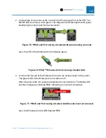
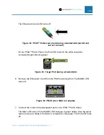
3. Connect the shielded plug end of the I-Cord to an incorrect port on the switch.
After a few seconds, the system recognizes the incorrect port. The Mode LED
will then change to a flashing RED, indicating an incorrect connection.
Figure 60: PM IU and Port during a Guided Add (far end incorrect connect)
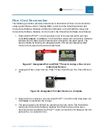
4. Disconnect the far end of the I-Cord from the incorrect port. The MODE LED
becomes solid green.
Figure 61: PM IU and Port during a Guided Add (far end incorrect connect
removed)
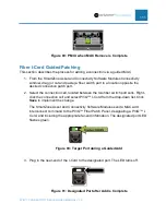
5. Connect the far end of the I-Cord to the proper port on the switch. The Mode LED
will change to a flashing amber, indicating a single-ended connection.
Figure 62: PM IU and Port during a Guided Add (far end connect)
On the PViQ™ Patch Panel, the Port LED to which the cable should be
connected begins flashing green.