38
■
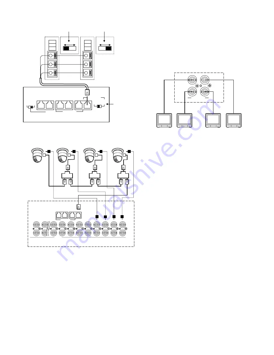
Connection with the Monitors
Connect the monitors to the MONITOR OUT connectors at
the unit's rear panel with the coaxial cable.
The connectors MONITOR OUT 1 to 4 are associated to
Monitor 1 to 4. When you control the monitors from a PS·
Data controller, the connectors MONITOR OUT are associ-
ated to Unit 1 to 4.
Martix Switcher
Monitor 1
Monitor 2
Monitor 4
Monitor 3
2
1
4
3
MONITOR OUT
(A)
(B)
GND
OFF
ON
(A)
(B)
GND
OFF
ON
WV-CPR450 and others
Set it to 2 or 4
(the same as
the connected
equipment).
The switch on a daisy-
chain-connected unit
other than the
extremities must be set
to OFF.
The switch on the end
unit should be set to
ON.
(For the termination
switch positions, refer
to the operating
instruction of the
corresponding unit.)
Matrix Switcher
2
DATA 3 DATA 2
TERM
OFF
ON
4
RS485(CAMERA)
LINE
SELECT
RS485(CAMERA)
PS•DATA
DATA 4
DATA 1
DATA HDR
Auto termination works inside the matrix switcher.
Matrix Switcher
CAMERA
1
1
2
2
3
3
DATA 3 DATA 2
OUT
IN
4
4
5
5
6
6
7
7
8
8
9
9
10
10
16
16
RS485(CAMERA)
DATA 1
Unit address 1
Unit address 2
Unit address 3
Unit address 4
Set the same
number for the
camera's unit
address as and
CAMERA IN.
Summary of Contents for WJ-SX 150A
Page 8: ...9 FEATURES OF THE MATRIX SWITCHER SYSTEM ...
Page 22: ...23 DETAILED PRODUCT DESCRIPTION ...
Page 29: ...31 INSTALLATIONS AND SYSTEM CONNECTIONS ...
Page 54: ...57 WJ SX150A SETUP PROCEDURES ...
Page 100: ...103 OPERATING PROCEDURES TERMINAL MODE ...
Page 119: ...123 OPERATING PROCEDURES PS DATA ...
Page 125: ...129 EXPANDED FUNCTION ...
Page 147: ...151 APPENDIX ...


