


134 CHAPTER FOURTEEN
Records
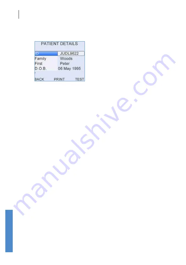
14.2.4
Review patient details in database
A non-editable version of highlighted
Patient Details
can be reviewed
by selecting
Detail
in the
Patient List
. Please refer to chapter
6
Patient
Details
for a full description of the screen format.
Select
Test
to start the test for this patient. Please refer to chapter
7
TEOAE Test
or
8
DPOAE Test
for an explanation on how to setup and
perform a test.
Select
Back
to exit
Patient Details
and return to the
Patient List
.
Records
Summary of Contents for Otoport Advance
Page 296: ...CHAPTER THIRTY TWO Index 296...


