Chapter 7: Side Lasers
This tells the system that the laser exists, and should be connected at startup.
The other parameters will be hidden unless this parameter is checked.
l
LaserX, LaserY, LaserZ: The location of the laser on the robot.
Measure to the sensing plane of each laser, which is about 20 mm from the top of the
sensor housing.
o
LaserX is mm, front-back, of the laser center from the robot’s idealized center of
rotation.
o
LaserY is mm, left-right, of the laser center from the robot’s idealized center of
rotation.
o
LaserZ is mm, from the floor to the center of the laser.
l
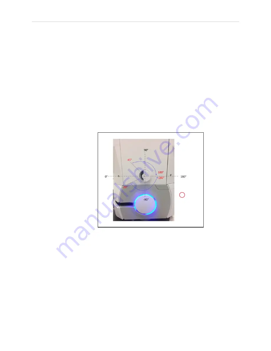
LaserIgnore: By default, the sensor scans an area of 270 degrees.
This area should be modified so that the laser does not sense parts of the AMR. Zones
entered here will be excluded from the search area.
A
Figure 7-5
Left Side Laser (Laser 4), (A) This Laser is Flipped Upside-Down
The format for the angles is startangle1: stopangle1, startangle2: stopangle2, etc.
Readings inside these angles will be ignored.
An example would be
-20:-180,45:180
l
LaserFlipped: For the laser on the left side of the robot, check the box.
This says the laser is upside-down, so the readings are interpreted correctly.
l
LaserType: Set this value to tim3XX unless otherwise requested.
l
LaserPortType: Set to serial when using the Aux Sensor connector.
l
LaserPort: The ports available on the Aux Sensor connector are /dev/ttyUSB5 and
13732-000 Rev J
LD Platform Peripherals Guide
121


