background image

Operation

4‐17

P/N 213828_11

 2014 Nordson Corporation

VersaBlue_PPA

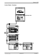
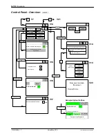
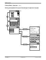
Control Panel - Overview - 

 (contd.)

Melter configuration

Select pressure build‐up or pressure
control for each pump

Field bus data protocol:

Standard

Melter configuration

PUMP 1

PUMP 2

Pressure
build‐up
feature

Pressure
build‐up
feature

V28

Pressure sensors

New sensor

P SENSOR A1

P SENSOR B1

P SENSOR A2

P SENSOR B2

NORDSON setup

Pressure sensor

setup

Melter configuration

IPC IP setup

0

Actual

ON

Calibrate

Pressure sensors

bar

P SENSOR A1

Pressure sensors

New sensor

V14

V21

V22

V25

Pressure sensor

setup

V23

Melter configuration

V26

V27

V24

1

1

IPC IP setup

Melter configuration

Melter

Request IP address via DHCP

Not en-

abled

Changes in this screen cause the IPC to re-boot by

itself.

255.255.255.0

192.168.0.99

IPC IP address

Subnet mask

Gateway address

Summary of Contents for VersaBlue VA

Page 1: ...NORDSON ENGINEERING GMBH L NEBURG GERMANY VersaBlueR Melters Types VA and VT Manual P N 213828_11 English Edition 06 14...

Page 2: ...elect Coat Select Cure Servo Flo Shot A Matic Signature Signature stylized Slautterback Smart Coat Smart Gun Solder Plus Spectrum Speed Coat Spirex Spraymelt Spray Squirt StediFlo Stratablend Super Sq...

Page 3: ...and Standards 1 2 User Qualifications 1 3 Applicable Industry Safety Practices 1 3 Intended Use of the Equipment 1 3 Instructions and Safety Messages 1 4 Installation Practices 1 4 Operating Practices...

Page 4: ...VA 2 3 Melter Type VT 2 3 Interface Standard I O 2 3 Interface Key to line 2 3 Application Head Gun Applicator 2 3 Residual Current Device RCD 2 3 Symbols 2 4 Melter Description 2 5 Illustration 2 5 S...

Page 5: ...r Control Modules 3 9 Connecting Filling Valve Option 3 9 Key to line Selecting Line Speed Voltage or Line Speed Current on I O Board 3 10 Interface Assignment 3 11 Interface Standard I O 3 11 General...

Page 6: ...and Numbering of Temperature Channels 4 18 Filling Tank 4 21 Manually 4 21 Level Display and Control Options 4 22 Automatic Tank Filling 4 22 Maximum Level 4 22 Recommended Temperature Setpoints 4 23...

Page 7: ...Manual Mode 4 66 Parameters Screen 1 Type of Motor Enable Adaptation to Parent Machine 4 68 Parameters Screen 2 Key to line 4 69 Parameters Screen 3 Motor OFF Delay Threshold Switch 4 70 Parameters Sc...

Page 8: ...t 5 10 Important for Mechanical Pressure Control Valve 5 11 Filter Cartridge 5 12 Replacing Filter Cartridge 5 12 Removing Filter Cartridge 5 12 Installing Filter Cartridge 5 13 Relieving Air with Air...

Page 9: ...ing Points 6 12 Warning Tank Overfilled 6 12 Warning Tank Level Low 6 12 Fault Tank Empty 6 12 Level Fixed Measuring Points 5 point Sensor 6 13 Warning Tank Overfilled 6 13 Warning Tank Level Low 6 13...

Page 10: ...lacing Variseal 7 14 Assembly Tool 7 14 Replacing Motor 7 15 Aligning Motor 7 16 Replacing Safety Valve 7 17 Installing Service Kit 7 17 Replacing Filter Cartridge 7 18 Observe when Performing Work be...

Page 11: ...Data 9 4 Dimensions 9 4 Options and Accessories 10 1 Accessories 10 4 Password A 1 Control Panel P N 207023 and P N 207850 First Generation B 1 Validity B 1 Visible Distinguishing Features B 1 Save R...

Page 12: ...Table of Contents X P N 213828_11 2014 Nordson Corporation VersaBlue_PPA...

Page 13: ...8940 49 4131 894 149 Nordson UV 49 211 9205528 49 211 9252148 EFD 49 6238 920972 49 6238 920973 Italy 39 02 216684 400 39 02 26926699 Netherlands 31 13 511 8700 31 13 511 3995 Norway Hot Melt 47 23 03...

Page 14: ...dson Phone Fax Africa Middle East DED Germany 49 211 92050 49 211 254 658 Asia Australia Latin America Pacific South Division USA 1 440 685 4797 China China 86 21 3866 9166 86 21 3866 9199 Japan Japan...

Page 15: ...ment can result in personal injury including death or damage to equipment or property Safety Alert Symbols The following safety alert symbol and signal words are used throughout this document to alert...

Page 16: ...overning regulations Contact the authority having jurisdiction for information Maintain safety information including the safety labels affixed to the equipment in readable condition Instructions Requi...

Page 17: ...function are physically capable of performing their job function and are not under the influence of any substance that degrades their mental capacity or physical capabilities Applicable Industry Safet...

Page 18: ...he required installation configuration does not match the installation instructions contact your Nordson representative for assistance Position the equipment for safe operation Observe the requirement...

Page 19: ...NOTE MSDSs for cleaning compounds that are sold by Nordson are available at www nordson com or by calling your Nordson representative Confirm the correct operation of all safety devices before placing...

Page 20: ...the equipment system 2 To prevent the equipment from being accidentally energized lock and tag the disconnect switch es or circuit breaker s that provide input electrical power to the equipment and o...

Page 21: ...on melter read and comply with the material s MSDS Ensure that the material s processing temperature and flashpoints will not be exceeded and that all requirements for safe handling ventilation first...

Page 22: ...to the solenoid valve s can result in personal injury HM CA PC WARNING Risk of electrocution Even when switched off and electrically isolated at the disconnect switch or circuit breaker the equipment...

Page 23: ...e Nordson melters are specifically designed to process polyurethane reactive PUR hot melt Attempting to process PUR in equipment not specifically designed for this purpose can damage the equipment and...

Page 24: ...nsing handguns by their proper suspension point First Aid If molten hot melt comes in contact with your skin 1 Do NOT attempt to remove the molten hot melt from your skin 2 Immediately soak the affect...

Page 25: ...e text of any safety instruction that appears on the labels as well as the meaning of the symbols that appear without any safety message The installation kit supplied with the melter contains printed...

Page 26: ...us burns 2 optional 7 1025326 CAUTION Hot surface Failure to observe can cause burns 3 290083 ATTENTION Risk of electrical shock Failure to observe may result in personal injury death or equipment dam...

Page 27: ...y insulating material The spark causes a very short high pulse of electrical current Plastic tool grips can cause electrostatic potential differences which can damage sensitive components A charge fro...

Page 28: ...Safety Instructions 1 14 P N 213828_11 2014 Nordson Corporation VersaBlue_PPA...
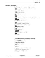
Page 29: ...MC In regard to electromagnetic compatibility EMC the melter is intended for use in industrial applications Operating Restrictions When operated in residential or commercial areas the melter may cause...

Page 30: ...ty valve may malfunction due to hardened or charred material Note on Manual The IPC Generation II has been replaced with the new model Generation III software version 6 00 000 All of the instructions...

Page 31: ...XS5 2 with the option Separate line speed signal inputs NOTE Key to line is also referred to as Automatic mode in Nordson literature In key to line the motor pump speed is proportional to the speed of...

Page 32: ...Introduction 2 4 P N 213828_11 2014 Nordson Corporation VersaBlue_PPA Symbols Original state Nordson default Original setting of parameters that can be reset to the defaults by touching Reset...

Page 33: ...2 Electrical cabinet 3 Main switch 4 Control panel 5 ID plate 6 Hose receptacles 7 Tank lid 8 Protective panel removable 9 Tank 10 Pressure control valve 11 Filter cartridge 12 Motor 13 Coupling 14 G...

Page 34: ...melted at a low temperature The material is then heated to processing temperature in the reservoir 3 Pressure Control Valve The mechanical pressure control valves 3 can be manually adjusted from 5 to...

Page 35: ...rial Flow Fig 2 4 Cross sectional view of the reservoir principle drawing Labeling with Two Pumps The connecting locations on the melter are labeled with numbers 2 1 on the manifold means motor pump 2...

Page 36: ...Standard I O 6 Interface Pneumatic pressure control and Bypass control option 7 Pressure displays Pneumatic bypass pump 1 and 2 option 8 Pressure display Inert gas option 9 Light tower option 10 Circ...

Page 37: ...ling signals for a filling valve With the option Level display fixed measuring points a 5 point sensor is built in A contact Fill tank is made available at the interface Standard I O The short level s...

Page 38: ...re sensor measuring transducers 1a are located on the plate below the manifold 1a 1b Pressure Display The melter outlet pressure is displayed and monitored Alarms for underpressure and overpressure ar...

Page 39: ...ng GmbH Lilienthalstr 6 D 21337 L neburg Germany www nordson com Serial No 3 4 5 1 2 Year LISTED US C UL Fig 2 9 Example 1 Melter designation 2 Order number 3 Configuration code 4 Electrical connectio...

Page 40: ...Introduction 2 12 P N 213828_11 2014 Nordson Corporation VersaBlue_PPA...
Page 41: ...s If possible use the pallet 3 that came with the melter and use angle brackets 2 to fasten the melter Use a sturdy box 1 or the folding box 4 Fig 3 2 to protect from damage Protect from humidity and...

Page 42: ...responds to the stated Degree of Protection Refer to section Technical Data Do not set up in a potentially explosive atmosphere Protect from vibration Protect the control panel from direct sunlight Th...

Page 43: ...Keep cables and hoses out of the space under the melter Position the unit such that air can circulate sufficiently under the melter Exhausting Material Vapors Ensure that material vapors do not exceed...

Page 44: ...lter tower Installation Personnel s Experience The instructions contained in this section are intended for personnel with experience authorization in the following fields Application methods with hot...

Page 45: ...t 30 mA Laying Cable ATTENTION Use only temperature resistant cable in warm areas of the equipment Ensure that cables do not touch rotating and or hot melter components Do not pinch cables and check r...

Page 46: ...400 VAC 3 phase without neutral Delta 480 VAC 3 phase without neutral Delta 230 VAC 1 phase with neutral Refer to wiring diagram for connecting arrangement Mains Filter Installing Kit Accessory ATTEN...

Page 47: ...e hoses The connections are protected with a clamp NOTE For more than one hose Every hose connection is allocated to a corresponding receptacle Do not mistakenly exchange Refer to wiring diagram for c...

Page 48: ...material softens 3 Connect the hoses in the order of the numbers on the manifold This prevents the creation of dead space that would otherwise result from unused connections Close unused hose connecti...

Page 49: ...le density 1 mg m3 Max pressure dew point 40 C 40 F Max oil concentration 0 1 mg m3 Connecting Filling Valve Option 1 Connect customer s compressed air supply to the control air connection 2 4 to max...

Page 50: ...urrent ranges 0 to 20 mA and 4 to 20 mA The DIP switch SW 4 on the I O board is used to switch between voltage and current The following tables indicate the original state when delivered by Nordson NO...

Page 51: ...viation is 10 In the field bus based control modes Field bus and Dual option Field bus communication the melter cannot be controlled via this interface NOTE optional Digital inputs Pin Input Function...

Page 52: ...Contact closed Motor 1 running Contact open Motor 1 not running 18 19 Make contact Contact closed Motor 2 running Contact open Motor 2 not running 20 Pin 21 to 24 not assigned 25 24 VDC External cust...

Page 53: ...pulses revolution 10 mm 772051 Encoder 500 pulses revolution 3 8 in 772052 Cable 9 m 30 ft 772054 Cable 18 m 60 ft XS5 Connection example Cable P N 772052 Encoder P N 772050 P N 772051 Pin Input Funct...

Page 54: ...of separate overflow protection 2 0 VDC 3 24 VDC 2 A Fill tank Signal to filling valve Additionally with level control with overflow protection Tank is overfilled contact open when level is exceeded 4...

Page 55: ...nsmission ratio operating air pressure material pressure of 1 15 1 Pressure display Pump 1 with options Manual pneumatic pressure control and Bypass control 2 Pressure display Pump 2 with options Manu...

Page 56: ...onal Valve The proportional valves for automatic pneumatic pressure control are located in the melter tower DIP switch SW1 to switch between 0 10 V and 4 20 mA 0 10 V Timer Relay The voltage supply to...

Page 57: ...ay An additional solenoid valve P N 401116 164Y8 in the air supply is linked to the signal System ready Wiring diagram page SLP 164b The timer relay 164K6 is located in the left door of the electrical...

Page 58: ...si 1 Pressure display Inert gas 2 Pneumatic safety valve 3 Connection Inert gas The safety valve for pneumatics limits the inert gas inlet pressure to 2 bar 200 kPa 29 psi 1 Fig 3 16 Tower and inert g...

Page 59: ...lines and remove 2 Swivel melter tower open 3 Guide cable through the resulting hole 4 Use the two screws M4 to fasten the light tower 5 Guide the cable through the top opening of the melter tower an...

Page 60: ...ivate the light tower the new software configuration code must be entered with all other versions it should be entered Box 17 Code W Refer to section Operation Key Melter configuration V26 in the over...

Page 61: ...ample VA012 with one pump and three hoses heated hoses not shown Retrofitting Pressure Sensors Refer to section Repair Replacing Pressure Sensor Retrofitting a Temperature Control Board Refer to the s...

Page 62: ...Installation 3 22 P N 213828_11 2014 Nordson Corporation VersaBlue_PPA...
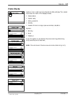
Page 63: ...Webserver The user interface is the same as the control panel Refer to Operation via the IPC Webserver at the end of this section Channel Numbers On the Control Panel The numbers of the temperature ch...

Page 64: ...Transparent Keys If a feature e g pressure control is available according to the melter configuration but contradicts the feature currently selected on the control panel e g speed control all of the k...

Page 65: ...etailed information General information Return to previous level Cancel and close when in input windows To next previous screen Confirmation acceptance of a value Backspace delete Page up down Increas...

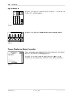
Page 66: ...ue_PPA Input Window When a field for entering a numerical value is touched this input window with the limits Min and Max appears When a field for entering a name is touched this input window appears S...

Page 67: ...t maintenance Heating hours until next maintenance Heating hours until next maintenance Heating hours until next maintenance Operation 4 5 P N 213828_11 2014 Nordson Corporation VersaBlue_PPA Status D...

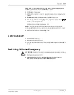
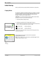
Page 68: ...on CAUTION Do not operate Nordson gear pumps without material Before switching on the motor ensure that the tank is filled 1 Fill the tank Refer to Filling the Tank 2 Set the main switch to I ON The m...

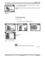
Page 69: ...d the starting screen appears on the control panel NOTE When the very first startup occurs password protection is not active default Control Panel Settings 4 Basic settings Language if necessary Engli...

Page 70: ...E To prevent excessive wear the motor pump speed should not continuously fall below 5 min 1 rpm or continuously exceed 80 min 1 rpm Refer to Control Panel Overview M1 If the motors are to be switched...

Page 71: ...y need to be adapted to the operating conditions Refer to Control Panel Overview V16 With software versions 6 47 035 and higher the maintenance interval can be switched on and off if it is to be activ...

Page 72: ...4 10 10 Switch on the motor s Fig 4 10 11 Purge the system M2 M1 M2 M1 Standard I O XS 2 All motors ON OFF collective enable Standard I O XS 2 Enable motor 2 Standard I O XS 2 Enable motor 1 Control...

Page 73: ...there Refer to Operation via the IPC Webserver for additional information After the First Day CAUTION Heating and cooling that occur during daily operation can cause screwed parts to loosen resulting...

Page 74: ...Operation 4 12 P N 213828_11 2014 Nordson Corporation VersaBlue_PPA...
Page 75: ...ault 10 220 50 230 51 Hose 1 230 GRID Temperature setpoints C C ALL RESERVOIR Hose 1 Gun 1 50 230 50 230 48 230 47 Hose 1 Status display 1 HOSE1 47 C Status display T1 T2 T3 Starting screen Hose 2 Gun...

Page 76: ...or 2 phase missing Grid Undertemperature warning Alarm history Alarm details Inactive at Ch1 Temperature sensor short circuit Active at 2005 08 30 11 00 12 V5 V6 Alarm history V1 V2 V3 V4 Ch1 Temperat...

Page 77: ...er standby Exit standby 1 2 3 4 02 00 06 00 06 30 12 00 13 00 22 00 15 00 15 30 19 00 19 30 Heaters on Heaters off Automatic enter standby after motor stop 60 min Not enabled Manual standby duration 6...

Page 78: ...t Level 2 parameters settings by trained personnel Level 3 basic settings Level 1 normal operation for all operators Screen cleaning System ready setup Units Password setup Profibus setup 100 System r...

Page 79: ...sensors New sensor P SENSOR A1 P SENSOR B1 P SENSOR A2 P SENSOR B2 NORDSON setup Pressure sensor setup Melter configuration IPC IP setup 0 Actual ON Calibrate Pressure sensors bar P SENSOR A1 Pressur...

Page 80: ...on Groups and Numbering of Temperature Channels A B C D E F G H Enabled Deactivated Select feature Define groups Standard I O Group Inputs A B C D E Input1 Input3 Input2 No input G H Input4 F No input...

Page 81: ...2 3 4 5 6 7 8 9 10 Internal internal Hardware Software External channel 1 External channel 2 13 14 15 16 17 18 13 14 15 16 17 18 13 14 15 16 17 18 Reservoir Grid Temperature control module 2 Temperat...

Page 82: ...e fault Overpressure warning Underpressure warning bar bar bar P SENSOR A1 1 2 rpm 80 0 Pump 1 rpm Pump 2 Key to line Key to line Pump 1 PID pressure control parameters Pressure sensor A M1 M2 M3 M4 M...

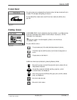
Page 83: ...ert gas equipment option Ensure that the inert gas inlet hole is not blocked with material Manually ATTENTION Hot Risk of burns Wear appropriate protective clothing equipment Tank and tank lid are hot...

Page 84: ...nged the level parameters on the control panel must be adapted to the new material Automatic Tank Filling Automatic tank filling is performed e g by a bulk melter connected to the optional filling val...

Page 85: ...approx 10 C 18 F below set processing temperature Undertemperature value fault 15 C 27 F below set processing temperature Air heater approx 20 C 36 F below set processing temperature Overtemperature v...

Page 86: ...rence channel prevents individual temperature channels from reaching their setpoint temperature long before the slowest temperature channel reservoir high melt reference channel It prevents hot melt m...

Page 87: ...t occurred Condition for Motor running All motors ON AND Enable motor When the system is ready again status display the motors can be switched on again via the control panel or the interface Standard...

Page 88: ...he main switch to I ON The melter begins to heat up EXCEPTION If the seven day clock is enabled and the melter is switched on heatup does not begin automatically Software version 6 00 000 and higher T...

Page 89: ...word protection Refer to Control Panel Overview V1 NOTE To prevent excessive wear the motor pump speed should not continuously fall below 5 min 1 rpm or continuously exceed 80 min1 rpm 6 Switch on the...

Page 90: ...re control Manual mode Key to line Option Field bus communication Beginning with the software version V5 02 004 there are two additional control modes available Field bus extended and Dual extended Th...

Page 91: ...on line Refer to Control Panel Overview V12 for information on entering text Service symbol A wrench lights up Refer to Control Panel Overview V16 The scan line can show The actual values of the activ...

Page 92: ...emperature default settings are different beginning with software version 6 47 035 Grid and reservoir 150 C 302 F Hose 1 Gun 1 Deactivated or 150 C 302 F if activated All other channels Deactivated or...

Page 93: ...to move to the first temperature channel of the selected application group Example Increase Setpoint Temperature 1 Touch to select Hose 1 2 Press 10 times or hold it down to increase the temperature...

Page 94: ...oring of Heatup and Cooling When the ALL ALL HOSES and ALL GUNS groups are used the values for warning and fault are always assumed together even if only one of the values has been changed This ensure...

Page 95: ...therefore cannot be changed Example Standard Melter Setpoint temperature 170 C 338 F Overtemperature fault 60 C 108 F This results in Fault Overtemperature at 230 C 446 F Overtemperature shutdown at 2...

Page 96: ...xed max temperature value for overtemperature shutdown and fixed max temperature value for fault Overtemperature Fixed max temperature value for warning Overtemperature Max temperature for setpoint Mi...

Page 97: ...e This causes an alarm to be triggered when the heatup phase is longer than anticipated The same applies to the overtemperature alarm values during the cooling phases Temperature Time Setpoint 2 Setpo...

Page 98: ...e at least reached after time Y an undertemperature fault is issued The same applies accordingly to the cooling phase This has the advantage that Changing the setpoint Switching on cold application gr...

Page 99: ...Normal state of a channel during operation Activated channels can be switched to display or control mode NOTE Temperature channels for reservoir and grid can not be deactivated Deactivated Control mo...

Page 100: ...en 3 To be set if heating the last 5 C 9 F up to the setpoint takes too long possible with a very high temperature setpoint To be set if the temperature swings above the setpoint during heatup possibl...

Page 101: ...enabled with the key Switch all motors on off collective enable AND via the interface Standard I O with the signal All motors ON collective enable Switching On If there are individual enables the mot...

Page 102: ...N The main contactor closes The power supply to the heaters and motors is switched on The heatup phase begins NOTE When the heaters have been switched off the control unit continues to be supplied wit...

Page 103: ...213828_11 2014 Nordson Corporation VersaBlue_PPA Melter contd Alarm Log Also refer to Channel Numbers at the beginning of this section Only the active alarms are shown here meaning alarms that have be...

Page 104: ...versions Fig 4 41 V6 1 Operation 4 42 P N 213828_11 2014 Nordson Corporation VersaBlue_PPA Melter contd Information Melter and Control System Total hours with heaters on This value indicates the hour...

Page 105: ...he interface 3 Select feature Deactivated or Standby 4 Switch application group s Switch Application Group s Temperature channels except for grid and reservoir can be combined to application groups A...

Page 106: ...the scan line of the starting screen Of the eight possible application groups four can be switched via the control panel as well as via the interface Standard I O the others can be switched only via...

Page 107: ...of the eight possible application groups A to H can be assigned to the four corresponding inputs of the interface Standard I O Also refer to section Installation The desired input for the application...

Page 108: ...aters and standby can be controlled via the seven day clock Up to four schedules that run at the same time can be stored for each day of the week Clear All of the schedules for the marked day in this...

Page 109: ...t date and time can be set with the keys The date is shown in the following format YYYY MM DD Y year M month D day NOTE The time is not automatically changed to and from daylight savings time Importan...

Page 110: ...c enter standby for this purpose Manual Exit Automatic standby is exited by the operator on the control panel Manual standby duration is ineffective here Automatic enter standby after motor stop Not e...

Page 111: ...The inert gas control is used to turn on off the solenoid valve of the inert gas equipment Gas on duration 5 s Gas off duration 30 min Change Language Touch the flag to switch languages There are CE...

Page 112: ...tomer Recipes Save recipe The operator must enter a name max 8 characters under File To better identify the individual recipes information such as the name of the application can be entered under Desc...

Page 113: ...en as soon as the level reaches or falls below the value Start at Filling continues until the level has reached or exceeded Stop at All values are shown as a percentage of the tank volume The status d...

Page 114: ...ntil the measuring point Stop filling is reached The status diode Filling is illuminated during filling Filling the warning Tank level low and the fault Tank empty can only be triggered when the heate...

Page 115: ...processing temperature permitted Setting range Standard melter 40 to 230 C 100 to 450 F High temperature melter 40 to 250 C 100 to 480 F Automatic heatup upon melter start automatic heatup upon melte...

Page 116: ...ters NOTE Every security level also applies to the lower ones Example The password for level 2 also grants access to the features of level 1 When the passwords have been assigned a security level must...

Page 117: ...50 or 100 selectable Contrast adjustable in increments of 2 Due to the improved display with software version 6 00 000 and higher only the brightness is adjustable Screen Cleaning The screen can be c...

Page 118: ...ol is switched off 500 h total hours with heaters on Software Version 6 47 035 and Higher Service Interval Setup The maintenance interval can be switched on and off with the wrench symbol When it is s...

Page 119: ...n the gateway located in the electrical cabinet EtherNet IP The IP address can be set either with the DIP switches on the gateway or via a PC Profinet IO The IP address can be set on a PC Refer to the...

Page 120: ...Webserver Parameter input only via control panel Line speed signal input via interface Key to line XS5 Field bus Control access only from master Control via the IPC Webserver and the interface Standa...

Page 121: ...d me last Operation via the interface Standard I O XS2 is not possible Parameter input can occur via the control panel or the IPC Webserver as well as via the master Line speed signal input via the in...

Page 122: ...possible On the control panel parameters can only be displayed Line speed signal input via the interface Key to line XS5 or via the field bus AND link for switching on the motors Field bus Melter con...

Page 123: ...or via the interface Standard I O Line speed signal input via the interface Key to line XS5 or via the field bus AND link for switching on the motors M2 M1 Field bus Melter control Enable motor 1 Fie...

Page 124: ...ptions Brightness and contrast Date and time Local language IPC IP address subnet mask and gateway address PROFIBUS address Passwords Selected line speed signal Customer text and other free texts such...

Page 125: ...re is enabled the IPC requests an IP address from the server The assigned IPC IP address the Subnet mask and the gateway address of the intranet are displayed but they cannot be changed Requesting IPC...

Page 126: ...es entered are the same the key to confirm is enabled After confirmation the system returns to the overview screen NOTE All of the configurations are saved on the memory board only when the key Confir...

Page 127: ...r is switched off it is removed from the assigned location and is available as a New sensor after a short time CAUTION Do not switch off the melter during assignment as long as the ON OFF key appears...

Page 128: ...ite The system is ready for operation rpm revolutions per minute Key to lin e Selecting Key to line or Manual Mode In manual mode the motor runs at the set speed in key to line it runs at the speed de...

Page 129: ...on off individual enable AND via the interface Standard I O with the signal Enable motor The indication lamp in the key can be different colors Gray off No motor enable on the control panel Yellow The...

Page 130: ...79 Depending on the control mode the control panel may be deactivated only parameter display is possible Enable motor via Control Panel Interface for line speed When a field bus based control mode fie...

Page 131: ...one voltage is possible as the line speed signal Parameters Screen 2 Key to line To M2 2 This key is available only with separate line speed signal inputs option NOTE The graph does not change to adap...

Page 132: ...ifying the product if the sensor distance to the applicator needs to be considered Fig 4 99 Product identification If this feature is not activated delay 0 s the motor stops as soon as it is switched...

Page 133: ...value When the upper threshold value is exceeded the motor starts when the value falls below the lower value the motor stops Start at 10 0 Stop at 5 0 Parameters Screen 4 Pressure Alarms Switching Bet...

Page 134: ...y Fig 4 102 With the option Pressure control the values are differential values for sensors A and B Fig 4 103 and absolute values for the sensors C Fig 4 102 Actual value 0 bar Max sensor measuring ra...

Page 135: ...fault 15 bar 1500 kPa 218 psi Overpressure warning 10 bar 1000 kPa 145 psi Underpressure warning 0 bar 0 kPa 0 psi Pressure Sensor C Unlike pressure sensors A and B the pressure sensors C are not assi...

Page 136: ...Manual Mode In manual mode the operator has control over the motors The pump speed is equal to the setpoint and does not change Speed setpoint 5 min 1 Example Increase Pump Speed Setpoint Prerequisite...

Page 137: ...x in key to line mode The frequency at maximum line speed is then 100 b Voltage 0 to 10 VDC Setting on the I O board Voltage Settings on the control panel Key to line signal Analog voltage Max in key...

Page 138: ...Pressure Control Key to line NOTE The graph does not change to adapt to the entered values Pressure values stated as a percentage refer to the measuring range limit of the pressure sensor used e g 80...

Page 139: ...7 Operation 4 77 P N 213828_11 2014 Nordson Corporation VersaBlue_PPA Motor contd PID pressure control t PID Pressure Control Parameters NOTE Should be adjusted only by personnel with experience in me...

Page 140: ...up As soon as the line speed signal exceeds the value plus 5 15 in the example the melter returns to speed controlled mode The appearance of the motor LED changes from a single color to two colors as...

Page 141: ...urer Flash point Processing temperatures Setpoints Grid Reservoir Filling valve Option Hose accessory 1 2 3 4 5 6 7 8 Applicator accessory 1 2 3 4 5 6 7 8 Air heater accessory 1 2 3 4 5 6 7 8 Speeds p...

Page 142: ...Operation 4 80 P N 213828_11 2014 Nordson Corporation VersaBlue_PPA...
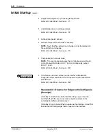
Page 143: ...ddress 192 168 0 99 Change to IPC IP address 192 168 0 100 IPC IP address 192 168 0 99 IPC IP address 192 168 0 99 Change to IPC IP address 192 168 0 101 Fig 4 111 IP addresses in a network Example We...

Page 144: ...s EtherNet cable is not used to transfer data on the field bus described in the separate field bus document section EtherNet IP Fig 4 112 Connecting EtherNet Cable 6 3 4 2 1 5 4 7 Fig 4 113 1 Release...

Page 145: ...there is no risk of stumbling over it 10 Switch on the melter again 11 Call up melter VersaWeb NOTE On the Product Resource CD there is a programming example MultiVersaWeb how to call up up to six mel...

Page 146: ...cipe versions of the old and new software are compatible NOTE With software version V5 00 000 and higher older recipes from version 3 or higher corresponds to software version y V3 20 013 can be accep...

Page 147: ...ustomer text RECIPE 1 05 09 05 TEXT 1 RECIPE 2 07 09 05 TEXT 2 File Description Recipes RECIPE 3 V7 V12 Fig 4 116 2 Touch the Browse key under Upload customer recipe on the PC Browse Fig 4 117 A file...

Page 148: ...version too old version modified by customer is uploaded via the Webserver an error indication appears on the control panel 6 Close the browser window 7 Load the desired recipe on the control panel R...

Page 149: ...elter is heated up Relieving Adhesive Pressure ATTENTION System and material pressurized Relieve system of pressure before disconnecting hoses applicators and hot melt handguns Failure to observe can...

Page 150: ...heduled maintenance tasks may prove necessary Resetting Maintenance Interval When the time that the customer has defined as the Maintenance interval has elapsed a warning is indicated software version...

Page 151: ...ned or charred material is stuck to the membrane clean separating membrane if necessary Every time pressure sensor is removed more frequently if necessary 5 21 Pressure control valve Replace outer O r...

Page 152: ...ter s Degree of Protection when cleaning Refer to section Technical Data CAUTION Do not damage or remove safety labels Damaged or removed safety labels must be replaced by new ones Remove material res...

Page 153: ...unction Tests During power up of the melter the lights in the light tower are all switched on briefly as a test The operator should check whether all lights function properly Replace defective lamps D...

Page 154: ...es indicated by the arrow Do NOT fasten a hook here Tighten the screws carefully to prevent damage to the injection PEM nuts Fig 5 3 Top view Fan and Air Filter Depending on dust accumulation the filt...

Page 155: ...hten the gland approx of a revolution in the operating direction of the pump If tightening is no longer possible the gear pump must be replaced Replacing Pump Shaft Seal When the pump shaft seal needs...

Page 156: ...ant manufacturer Mineral oil CLP 220 AGIP Blasia 220 ARAL Degol BMB 220 or Degol BG 220 BP Energol GR XP 220 DEA Falcon CLP 220 ESSO Spartan EP 220 or GP 90 KL BER Kl beroil GEM 1 220 OPTIMOL Optigear...

Page 157: ...lubricant NOTE Properly dispose of the old lubricant according to local regulations 6 Wash out casing with suitable cleaning agent and remove lubricant residue 7 Clean the mounting surfaces 8 Measure...

Page 158: ...rature ATTENTION Hot Risk of burns Wear appropriate protective clothing equipment 2 Relieve melter pressure 3 Close compressed air supply 4 Refer to Measuring Insertion Depth 4 Unscrew air hose 5 Use...

Page 159: ...sertion Depth Measure and make a note of the insertion depth of the setting screw dimension X This way the insertion depth can be replicated after reassembly Adjusting Setting Screw Adjust the setting...

Page 160: ...s keeping a supply of filter cartridges on hand to prevent disruptions in production NOTE Remove the filter cartridge when the melter is hot and not under pressure M10 Size 24 Fig 5 6 CAUTION Stop tur...

Page 161: ...lowing the pump to run until the material comes out of the hose port or applicator free of bubbles or relieve air through the relief valve if there is one Refer to Relieving Air with Air Relief Valve...

Page 162: ...Thread 4 Filter sheath 5 Filter screen 6 Nut 7 Hexagon nut locknut Assembling Filter Cartridge 1 Clamp the filter screw vertically in a vice 2 Carefully inspect O rings replace if necessary 3 Assembl...

Page 163: ...er sheath 6 Filter screen 7 Filter nut 8 O ring 44 x 3 9 Locknut filter cartridge Assembling Filter Cartridge 1 Clamp the filter screw vertically in a vice 2 Carefully inspect O rings replace if neces...

Page 164: ...ge Installing Service Kit Each kit contains O rings filter sheath filter screen and high temperature grease Required tools M10 screw with suitable wrench Open end wrench size 24 Pliers Torque wrench s...

Page 165: ...The inside of the tank is release coated Do not use metallic tools to clean Do not use wire brushes This could damage the release coating Retightening Fixing Screws Heating and cooling that occurs du...

Page 166: ...epair 4 Release the four fixing screws M8 from the safety valve plate and remove plate 5 Remove old O rings and when present the filter screen in the suction hole 6 Clean sealing surfaces on tank safe...

Page 167: ...erating temperature ATTENTION Hot Risk of burns Wear appropriate protective clothing equipment 2 Empty tank 3 Release four Allan screws M5 and lift off plate Use a pliers to extract the tank isolation...

Page 168: ...full motor speed and with hose connections closed Switch the motor on and off several times Changing Type of Material 1 Run the melter until empty 2 Before changing the type of material determine whe...

Page 169: ...ing membrane arrow Fig 5 18 Never use hard tools Whenever possible remove material residue only with a cleaning agent recommended by the material supplier Thermoplastic substances such as hot melt adh...

Page 170: ...list to later order a brass washer In addition to the instructions under Screwing In observe the following The brass washer seals by deforming Before extracting the pressure sensor ensure that the ol...

Page 171: ...s in production NOTE Replace only when the control module is warm and the material is soft approx 70 C 158 F depending on material ATTENTION System and adhesive pressurized Relieve system pressure Fai...

Page 172: ...rt gas equipment are located in the melter tower Performance Check The performance of the safety valve should be checked approx every six months Do this by turning the knurled screw counterclockwise u...

Page 173: ...r part Activity Date Name Date Name Date Name Complete melter external cleaning Visual inspection Gear pump Motor gear box Fan air filter Tank Pressure control valve Filter cartridge Safety valve Safe...

Page 174: ...Maintenance 5 26 P N 213828_11 2014 Nordson Corporation VersaBlue_PPA...
Page 175: ...and regulations concerning energized unit components active parts Failure to observe may result in an electric shock Helpful Tips Before starting systematic troubleshooting check the following Is the...

Page 176: ...tatus Green Yellow Red Status display Warning The operator must decide whether the situation is critical for the application and action is required The system remains ready for operation 6 Service int...

Page 177: ...to the melter can be checked Refer to Checking Transmitted Field Bus Data 5 Temperature controller output short circuit 10 Tank is empty 16 Level sensor defective 5 point sensor transmits a faulty si...

Page 178: ...ellow Red Status display Shutdown Shutdown turns the melter off main contactor opens 1 Main contactor thermostat fault Main contactor defective Main contactor switches incorrectly due to wrong wiring...

Page 179: ...Bus terminating resistor missing or defective 13 Temperature controller incorrect software version The firmware version of the controller installed is not compatible with the IPC program version 20 C...

Page 180: ...ault Undertemperature Overtemperature shutdown by tank thermostat Fixed max temperature value for overtemperature shutdown and fixed max temperature value for fault Overtemperature Fixed max temperatu...

Page 181: ...the setpoint by more than the differential value Undertemperature warning delta for longer than 5 seconds Automatic Reset The temperature has increased to 2 C 3 6 F below the setpoint Overtemperature...

Page 182: ...perature has exceeded the setpoint minus the differential value Undertemperature fault delta by 2 C 3 6 F Overtemperature Fault Triggered 1 The temperature has exceeded the setpoint by more than the d...

Page 183: ...265 C 510 F was exceeded for longer than 5 seconds NOTE Channels in display mode trigger shutdown only when they have reached the maximum temperature of 245 C 475 F for standard melters or 265 C 510 F...

Page 184: ...ssure Sensors A and B The pressure has fallen below the setpoint by more than the differential value Underpressure warning for longer than 20 seconds The motor assigned to the pressure sensor has rece...

Page 185: ...ntial value Overpressure warning Pressure Control Pressure Sensors C Speed Control Pressure Display Pressure Sensors A B and C The pressure has exceeded the absolute value Overpressure warning for mor...

Page 186: ...ed Level Variable Measuring Points Warning Tank Overfilled The warning is triggered as soon as the level has reached or exceeded 98 for longer than 5 seconds This is a fixed internal value Automatic R...

Page 187: ...level falls below the measuring point Tank level low for longer than five seconds a warning is triggered Automatic Reset When the measuring point is reached Fault Tank Empty When the level falls below...

Page 188: ...s 6 24 VDC power supply defective Replace 7 IP address was assigned twice in the network Check the IP addresses and set a unique IP address for each node One Channel does not Heat Possible cause Possi...

Page 189: ...Memory Board 2 Control panel dark or bright Brightness setting was changed Use to adjust Refer to section Operation 3 Control panel does not function react Hardware defective For spare parts numbers r...

Page 190: ...up protection activated Standby entered Switch on the motor s again Undertemperature during operation 5 Speed rpm not set The parameter Max pump speed in key to line is on 1 min 1 Set the speed Refer...

Page 191: ...ive Replace 13 Motor not supplied with voltage Technical inspection 14 Motor controller fault Switch melter off and on again with main switch Motor overheated Refer to 11 Motor controller overheated D...

Page 192: ...e Refer to wiring diagram for assignment Hose applicator temperature channel not activated Activate on control panel Hose applicator heater defective Replace hose Replace heater cartridge s in applica...

Page 193: ...re too Low Possible cause Possible fault troubleshooting Corrective action 1 Gear pump is worn Replace pump 2 Safety valve does not close any more Replace 3 Pressure control valve dirty and thus clogg...

Page 194: ...ng Corrective action 1 Tank setpoint temperature set too high Correct temperature setting 2 Tank was not supplied with inert gas Check whether material supplier has prescribed inert gas With the optio...

Page 195: ...evenly Distribute such that the granulate is spread evenly around the sensor 3 Fault Level sensor failure at 5 point level sensor Wire broken or not plugged in Refer to LEDs of 5 point Sensor Evaluato...

Page 196: ...material No compressed air to control module or compressed air set too low Connect compressed air and set to correct value Control module defective Replace control module 2 Filling valve does not heat...

Page 197: ...signal for motor 1 X15 Line speed signal for motor 2 Digital Inputs Outputs LEDs Outputs LEDs 1 Lit for active output Inputs LEDs 2 Lit for active input FIN LED 3 Lit as soon as pulses 1 Hz at frequen...

Page 198: ...X13 4 E10 Application group 4 X13 6 E11 Main switch main contactor X13 8 E12 Reserved NOTE The LED indicates only that there is voltage at the I O board input it does not indicate whether the functio...

Page 199: ...nsmitted D14 No connection to control unit IPC D13 Lit Controller software reset Flashing CAN fault counter overflow stack error power down not finished properly D1 Heater output of the first channel...

Page 200: ...r motor controller is being parameterized Off Flashing every 0 4 s Overvoltage or undervoltage shutdown Off Off Missing voltage supply LED of Overflow Protection Evaluator LED Fault Red LED Full Flash...

Page 201: ...ng Blue bl 4 Yellow On Material covering 4th measuring point Stop filling Green gn 5 Yellow On Material covering 5th measuring point Tank overfilled Black bk 6 Green Power On Supply voltage present 7...

Page 202: ...ntrol panel is touched Off During booting 4 TOUCH ERROR red Illuminated During booting otherwise fault Flashing Control panel dirty Off Control panel touch panel ready 5 SUPPLY OK green Illuminated En...

Page 203: ...ay Data index decimal display Channel number decimal display Write data value decimal display When Extended is used Melter control 1 binary display Melter control 2 binary display Melter control 3 bin...

Page 204: ...Troubleshooting 6 30 P N 213828_11 2014 Nordson Corporation VersaBlue_PPA...
Page 205: ...ENTION Hot Risk of burns Wear appropriate protective clothing equipment Some melter components can only be detached when the melter is heated up ATTENTION System and material pressurized Relieve bulk...

Page 206: ...IBUS DP option 2 RJ45 EtherNet 3 Not in use 4 CAN plug 9 pin DSub male 5 RS232 plug 9 pin DSub male System port 6 24 VDC power supply Note If the system does not include the option PROFIBUS DP there i...

Page 207: ...s make a note of the pressure sensor assignment 3 Save and download the recipe Refer to section Operation Upload and Download of Customer Recipes 4 Switch the melter off with the main switch 5 Refer t...

Page 208: ...the communication assembly only when the IPC is deenergized 1 Fig 7 4 1 Unscrew the cover 1 Fig 7 4 and place aside for later use or unscrew and extract the old communication assembly 2 Carefully sli...

Page 209: ...Continue with On the Control Panel Allocating Replaced Motor Controllers MC to their Motors Replacing CAN Module of Motor Controller 1 Disconnect motor controller from power supply and wait at least 3...

Page 210: ...resistors are switched in parallel via the bus Thus when they are installed resistance measuring indicates a value of 60 On the Control Panel Allocating Replaced Motor Controllers MC to their Motors E...

Page 211: ...TE The screen can be scrolled up and down 2 Leave only ONE motor controller connected Disconnect all of the others from the power supply In this case Disconnect the operating voltage from MC 1 3 and 4...

Page 212: ...Repair 7 8 P N 213828_11 2014 Nordson Corporation VersaBlue_PPA Attaching Shielding Plate EMC 1 2 3 4 red black blue white bare 63N5...

Page 213: ...espond to wiring diagram page SYS 3 Then remove only the sheath from the pressure sensor line to expose the braided screen approx 20 mm 0 8 inch 4 Fold over the braided screen so that it overlaps the...

Page 214: ...Manifold T Tap new Procedure 1 Switch off the pressure sensor to be replaced P sensor 1 in the example Also refer to section Operation 2 Wait until the ON OFF key is no longer subdued 3 Disconnect th...

Page 215: ...emperature Pin in position 0 Closed Pin in position 1 Open Detaching Gear Pump 1 Close tank isolation valve 1 NOTE Detach the gear pump only when the material is soft approx 70 C 158 F depending on ma...

Page 216: ...high temperature grease to the fixing screws of the pump then tighten screws crosswise using a torque wrench the tank must be cold when screws are tightened Torque 25 Nm 220 lbin 3 Refer to Important...

Page 217: ...e parallel to one another If the axes lean towards one another excess load is applied to the edges of the bearings causing premature wear The coupling may not be twisted axially The intermediate disk...

Page 218: ...anyone besides a Nordson employee 1 Remove the gear pump from the melter but do not disassemble it Refer to Replacing Gear Pump in this section 2 Have a new seal and a suitable assembly tool ready Ass...

Page 219: ...ing apart CAUTION The bracket should not be slid back in the slot or unscrewed If this is unavoidable refer to Aligning Motor 6 Unscrew motor from bracket 1 7 Remove any protective varnish from the sh...

Page 220: ...arding Coupling in this section 2 Attach the coupling to the pump shaft without using force no jolts or pounding Torque 36 Nm 320 lbin 3 Insert the motor shaft 1 Fig 7 24 in the coupling such that the...

Page 221: ...emperature grease NOTE Screw in out only when the valve 2 Fig 7 25 and pump are warm and the material is soft approx 70 C 158 F depending on material Required tools Open end wrench size 19 Pliers Torq...

Page 222: ...al equipment cover 2 Release fixing screws and remove the old thermostat see arrows 3 If necessary clean the fastening point with a lint free cloth 4 With older melters VT the adapter plate 1 Fig 7 27...

Page 223: ...shers 3 and 5 and insulating cylinder 2 2 Remove all of the ceramic powder from the heater connection 3 Guide new insulating cylinder 1 into the heater connection 4 Attach new insulating cylinder 2 wa...

Page 224: ...and heat transfer compound Required tools Pliers Side cutting pliers V025 1 Remove electrical equipment cover 2 Disconnect connecting wires and extract old temperature sensor by the connecting wires o...

Page 225: ...s no and jumper settings are to be assumed from the replaced board The CAN address is set on the dials using a screwdriver I O Board CAN bus plug X16 Setting CAN Address Dial default Board no SW1 SW2...

Page 226: ...itch S4 Switching Bus Terminating Resistor ON OFF The terminating resistor is switched on and off with switch S5 The terminating resistor on the last temperature control board must always be switched...

Page 227: ...nction connected The operating ground must be linked to the metal casing of the melter along the shortest path Do not connect via ground conductor All potentiometers have 20 revolutions and no mechani...

Page 228: ...ation 4 into position 1 2 With potentiometer 1 2 find the switching point of the LED Calibration 3 LED just lights up Turn clockwise LED on Turn counterclockwise LED off 3 Plug jumper Calibration 4 in...

Page 229: ...ction All adjustments should be made with operating ground no ground conductor function connected The operating ground must be linked to the metal casing of the melter along the shortest path Do not c...

Page 230: ...ED full 6 flashes NOTE Skip step 2 if the LED state is already known 3 Turn potentiometer P3 to the left to the switching point green LED empty on red LED full off 4 From the switching point turn one...

Page 231: ...ath Do not connect via ground conductor All potentiometers have 20 revolutions and no mechanical limit stop meaning no fixed end position They can not be damaged by turning too far 6 5 4 3 2 1 7 8 9 1...

Page 232: ...pplied LED Operating voltage 6 lit 1 Turn potentiometer P3 10 Fig 7 41 until the LED Tank empty 1 Fig 7 41 just begins to light up 2 Turn back to the switching point when the LED Tank empty just goes...

Page 233: ...component Repair 7 29 P N 213828_11 2014 Nordson Corporation VersaBlue_PPA Replacing Coupling Component Option Separate Line Speed Voltage Fig 7 42 Always set the coupler component DIP switches to Inp...

Page 234: ...Repair 7 30 P N 213828_11 2014 Nordson Corporation VersaBlue_PPA...
Page 235: ...ns and other properties The points in the column Description show the relationship between assemblies subassemblies and single parts Quantity The quantity needed per unit assembly or subassembly The a...

Page 236: ...would be a special feature of level monitoring When necessary a supplement describing the special feature is added to the manual When appropriate a so called Delta n Parts List is added to the docume...

Page 237: ...mperature melter Measuring precision 1 C Material pressure standard 5 to 85 bar 500 to 8500 kPa 72 5 to 1 233 psi The pressure control valve is preset at the factory Default 35 bar 3500 kPa 508 psi De...

Page 238: ...e melter Shutdown by transformer thermostat 155 C 5 C 311 F 9 F Max operating temperature of filling valve option 230 C 450 F Electrical Data ATTENTION The unit is designed for only one operating volt...

Page 239: ...phase V12 All data at 230 VAC V12 V25 V50 V100 Max 2 pairs Total Per hose gun pair Per channel 2400 W 1800 W 1800 W Melter fuse protection V12 V25 V50 V100 Hose gun Hose gun Hose gun Hose gun 2 4 6 2...

Page 240: ...Dimensions mm Length x Width 885 x 585 885 x 585 1000 x 785 1100 x 1035 Tank opening mm With the option filling valve 191 x 165 62 x 165 227 x 267 95 x 267 232 x 459 232 x 308 306 x 685 306 x 418 Tank...

Page 241: ...X C G 14 15 16 17 18 19 20 21 22 Configuration code box 14 15 16 17 18 19 20 21 22 23 Options P A L W 1 D K C G C M B 2 N D F P 3 E G C C X P H E D X F Option in configuration code Box Also available...

Page 242: ...he pressure sensor converts the pressure to an electrical signal which is used for control via the CAN bus Pressure build up feature 14 E One pressure sensor per pump There is no pressure control valv...

Page 243: ...k for separate overflow protection Light tower 17 W Four colors Indicates operating mode of melter Main switch 18 1 red yellow 4 pin 2 black 3 pin 3 black 4 pin X Red yellow 3 pin standard Field bus c...

Page 244: ...Accessories Flap Valve For 8 mm 13 mm and 16 mm hose connections Adapter cable For connection to the interface Standard I O Mains filter Filters electromagnetic interference Safety valve 100 bar Repl...

Page 245: ...Speed setpoint Max pump speed pressure in key to line mode Level 2 Parameters Settings for trained personnel Undertemperature overtemperature warning fault Standby values Automatic enter standby Manua...

Page 246: ...max pump speed pressure Min pump speed pressure in key to line mode Threshold switch Restore default settings Melter configuration Control modes standard field bus field bus extended dual dual extend...

Page 247: ...riate remove this page and store in a safe location Customer Master Password For Nordson VersaBlue adhesive melters X5SW3HH User Name and Keyword For Nordson VersaBlue melters for operation via the IP...

Page 248: ...Password A 4 P N 213828_11 2014 Nordson Corporation VersaBlue_PPA...

Page 249: ...dix applies to melters with the above first generation control panels The P N of the control panel can be found on the ID plate The appendix describes the differences between the old model and the new...

Page 250: ...number Setting range resolution Melter 15 Melter status and alarms 0 Bit field R Bit 2 Value 1 Alarm IPC or coprocessor battery voltage low warning 0 No alarm Light tower colors Alarm no Status Green...

Page 251: ...tion Hardware defective Control panel dirty Clean as described in section Maintenance External Cleaning Control Panel 5 No EtherNet connection Wrong invalid IPC IP address set Correct the IP address o...

Page 252: ...3 Fuse 4 24 VDC power supply 5 Not in use 6 CAN plug 9 pin sub D male 7 RJ45 EtherNet 8 RS232 COM1 for options ControlNet and EtherNet IP 9 PROFIBUS DP option Detaching Control Panel 1 Lift one side...

Page 253: ...low remains after the control panel is started up 4 Switch the melter off and then on again The alarm IPC battery voltage low no longer appears Replacing Memory Board ATTENTION The memory board may b...

Page 254: ...A 19 D 394201 Battery 3V 950mAh Lithium RENATA CR2477N 1 729736 7116383 Memory Card IPC Software Version 1 00 000 Memory Card 1 00 000 IPC Software Version 3 30 020 Memory Card 3 30 xIPC Software Vers...

Page 255: ...Use and Unintended Use When in doubt please contact your Nordson representative Manufacturer Information Materials may be processed only when the manufacturer s product descrip tions and Safety Data...

Page 256: ...en materials require heating adherence to the prescribed processing temperature is imperative to ensure the quality of the application It may not be exceeded Overheating can cause material coking or c...

Page 257: ...mage of the application material applied to a surface unit of the substrate Determining the application weight A circle cutter is used to cut several 100 mm2 sized circles from the uncoated substrate...

Page 258: ...that is cast into a tank or melting plate This fixed connection provides optimal heat conducting Charring Decomposition of a synthetic material particularly through heat influence Can occur when proc...

Page 259: ...on the speed of the parent machine ControlNet Internationally standardized serial field bus with scanner and adapter subscribers Nordson melters adapter with a ControlNet interface can be controlled r...

Page 260: ...Newtonmeter Nm 8 85 Pound inch US lbin Newtonmeter Nm 0 74 Pound foot US lbft Pound inch US lbin 0 113 Newtonmeter Nm Pound foot US lbft 1 36 Newtonmeter Nm Pressure SI unit Pascal Pa N m2 Pascal Pa...

Page 261: ...renheit F Degrees Fahrenheit F F 32 1 8 Degrees Celsius C Viscosity dynamic SI unit Pascal second Pas Pascal second Pas 1 0 x 103 CentipioseA cP CentipioseA cP 1 0 x 10 3 Pascal second Pas Viscosity k...

Page 262: ...impurity protection Water protection Impact protection Protection from Protection from Protection from impact strength up to 0 1 Foreign object 50 mm Water dripping vertically 0 225 J Impact of 150 g...

Page 263: ...can only flow in one direction The valve closes automatically when the flow direction changes Free wheeling Diode Electronic component that protects electronic assemblies from power surges that occur...

Page 264: ...ive gas Initiator Component that generates a signal when an object is in a certain area of its surroundings Possible models are e g proximity initiators and light beam photo cells Intermittent Mode Mo...

Page 265: ...led by the customer s master Material General Nordson term for application materials such as thermoplastic hot melt adhesives adhesives sealants cold glue etc Melter Melts and feeds hot melt adhesives...

Page 266: ...bstrate and pressing on the second part Factors such as application temperature substrate adhesive properties and amount of adhesive are relevant to open time Operating Air Pressure The customer s com...

Page 267: ...le to stabilize is as short as possible PLC Programmable Logic Controller Polyamide A term used by Nordson to describe polyamide based hot melt adhesives Other common designations are polyamide resin...

Page 268: ...l local regulations Proportional Pressure Control Valve Electropneumatic component that enables control of pneumatic pressure with an electrical variable usually control voltage Protective Gas Refer t...

Page 269: ...r with waning signs on the unit Resistance Temperature Sensor Component with an electrical resistance the value of which changes as a factor of the temperature Nordson units use the models Pt 100 and...

Page 270: ...t melt manufacturer Substrate The product fabric foil etc to which a material is applied Tach Generator A component that generates electrical voltage pilot voltage The voltage is proportional to the s...

Page 271: ...voltage VDC Abbreviation for Direct Current DC voltage Viscosity Strength an indication of the force that must be generated to move a liquid 1 Viscosity also called dynamic viscosity Unit Pas Refer to...

Page 272: ...Glossary D 16 P N 213828_11 2014 Nordson Corporation VersaBlue_PPA...

Reviews: