3
2
1
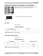
I/O
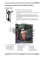
Fig. 7‐30
Inside of electrical cabinet door
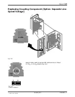
Fig. 7‐31
Dial
Repair
7‐21
P/N 213828_11
2014 Nordson Corporation
VersaBlue_PPA
Replacing I/O Board, Temperature Control Board
NOTE:
Switch / DIP switch settings, bus terminating resistors yes/no and
jumper settings are to be assumed from the replaced board.
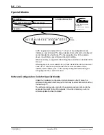
The CAN address is set on the dials using a screwdriver.
I/O Board
CAN bus plug X16
Setting CAN Address
Dial (default)
Board no.
SW1
SW2
0
5
1
NOTE:
Dial setting SW1 may not be changed.
Temperature Control Board
CAN bus plug X9
Setting CAN Address
Dial (default)
Board no.
Temperature channel
S1
S2
7
1
1
1 to 6
7
2
2
7 to 12
7
3
3
13 to 18
NOTE:
Dial setting S1 may not be changed.
Summary of Contents for VersaBlue VA
Page 12: ...Table of Contents X P N 213828_11 2014 Nordson Corporation VersaBlue_PPA...
Page 28: ...Safety Instructions 1 14 P N 213828_11 2014 Nordson Corporation VersaBlue_PPA...
Page 40: ...Introduction 2 12 P N 213828_11 2014 Nordson Corporation VersaBlue_PPA...
Page 62: ...Installation 3 22 P N 213828_11 2014 Nordson Corporation VersaBlue_PPA...
Page 74: ...Operation 4 12 P N 213828_11 2014 Nordson Corporation VersaBlue_PPA...
Page 142: ...Operation 4 80 P N 213828_11 2014 Nordson Corporation VersaBlue_PPA...
Page 174: ...Maintenance 5 26 P N 213828_11 2014 Nordson Corporation VersaBlue_PPA...
Page 204: ...Troubleshooting 6 30 P N 213828_11 2014 Nordson Corporation VersaBlue_PPA...
Page 234: ...Repair 7 30 P N 213828_11 2014 Nordson Corporation VersaBlue_PPA...
Page 248: ...Password A 4 P N 213828_11 2014 Nordson Corporation VersaBlue_PPA...
Page 272: ...Glossary D 16 P N 213828_11 2014 Nordson Corporation VersaBlue_PPA...

