background image

219

12

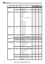
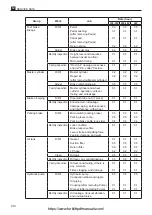
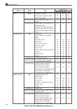
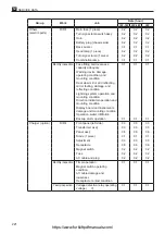
 SERVICE DATA 

Group

Work

Job

Rate (hour)

10P-18P 20P-28P

30P

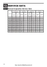
Control unit

R/R/I

Control unit ass'y removal / 
installation

1.5

1.5

1.5

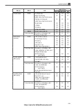
IGBT module (1 piece)
Add 0.2Hrs every time 1 piece is 
added.

0.7

0.7

0.7

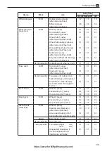
Sensor comp., current (1 piece)
Add 0.3Hrs every time 1 piece is 
added.

0.6

0.6

0.6

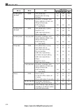
Capacitor (1 piece)
Add 0.2Hrs every time 1 piece is 
added.

0.8

0.8

0.8

Resister  (1 piece)
Add 0.3Hrs every time 1 piece is 
added.

0.8

0.8

0.8

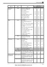
Sensor comp., heat (1 piece)
Add 0.3Hrs every time 1 piece is 
added.

0.7

0.7

0.7

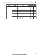
Capacitor (1 piece)
Add 0.2Hrs every time 1 piece is 
added.

0.6

0.6

0.6

MPU board (travel/hydraulic)

0.4

0.4

0.4

Fan comp (1 piece)
Add 0.3Hrs every time 1 piece is 
added.

0.5

0.5

0.5

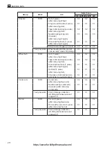
Confirmation

Travelling speed, lift speed, 
plugging distance.

0.5

0.5

0.5

Monthly inspection

Looseness in terminal contact 
area, looseness in wiring 
mounting area

0.1

0.1

0.1

Resistor and capacitor terminal 
looseness and burnout, fitting 
bolt looseness

0.1

0.1

0.1

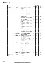
Yearly inspection

[Overcurrent limiter] 

(for hydraulic          A)

Motor lock current value 

(for travel               A)

0.1

0.1

0.1

[Safety device] Contactor 
operation
(pulling out arc or not)

0.1

0.1

0.1

Wiring looseness, damage, and 
clamp condition

0.2

0.2

0.2

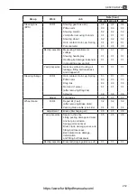
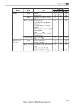
Accelerator

R/R/I

Accelerator

0.5

0.5

0.5

Monthly inspection

Accelerator pedal operating 
condition

0.1

0.1

0.1

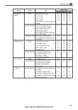
Display panel 
ass'y

R/R/I

Display panel ass'y

1.0

1.0

1.0

https://www.forkliftpdfmanuals.com/

Summary of Contents for FB10P

Page 1: ...ll the possible cases of accidents in this WORKSHOP MANUAL Therefore attention should be given to precautions other than the ones mentioned in this WORKSHOP MANUAL Especially when repair and maintenan...

Page 2: ...https www forkliftpdfmanuals com...

Page 3: ...a facility The work conditions described in the WORKSHOP MANUAL are written on the assumption that the work is performed at standard work facilities and tools for the maintenance of NICHIYU electric l...

Page 4: ...r arm inspection 44 3 3 3 Tie rod Comp inspection 44 3 3 4 Knuckle inspection 44 3 3 5 King pin inspection 45 3 3 6 Hub and hub bolt inspection 45 3 3 7 Rear axle Comp inspection 45 3 4 Troubleshootin...

Page 5: ...tank precautions 83 7b 2 2 Oil piping replacement precautions 83 7b 3 Inspection and adjustment 84 7b 3 1 Oil inspection 84 7b 3 2 Recommended oil and quantity 84 7b 3 3 Oil tank and filters cleaning...

Page 6: ...comp inspection and replacement Traction and Hydraulic motor 145 9 3 2 Armature comp inspection and replacement 146 9 3 3 Brush Brush holder and Spring EPS motor inspection and replacement 146 9 3 4 M...

Page 7: ...tion 182 10e 3 2 Earth inspection 183 10e 3 3 Reserve function inspection 183 10e 4 Charging procedure 184 10e 4 1 Automatic charge Daily charge 184 10e 4 2 Reserve charge 188 10e 4 3 Balancing charge...

Page 8: ...parts well CAUTION ADEQUATE SPACE WITH FLAT SURFACE lThe floor area of the shop location where inspection and maintenance are performed must have adequate floor space and have level surfaces without...

Page 9: ...klift truck support it with safety blocks or rigid stands WARNING l When hoisting a forklift truck or a heavy component use ropes or cable with correct capacity lDo not use ropes or cables which are k...

Page 10: ...ical operations CAUTION CHARGING BATTERY l Batteries produce flammable gas during charging Do not allow batteries in the vicinity of fire or flames Failure to observe the above could result in an expl...

Page 11: ...If the hydraulic motor runs high pressure is applied to all hydraulic circuits 5 You must sit on the seat and turn on the key switch to follow above steps 1 2 and 3 Otherwise the internal hydraulic p...

Page 12: ...0 Plate warning 1 Shearing point 5 50004 65180 Plate caution 1 Battery cover lock 6 24700 13490 Plate lubrication 1 Lubrication 7 38540 00630 Label caution 1 w battery SHINKOBE 38540 00520 w battery G...

Page 13: ...en valve lever operation at a high lift 5 Do not run sideways or handle on an incline 6 When the red lamp of battery capacity indicator turns on charge battery 7 Check electrolyte every week and reple...

Page 14: ...checking and maintaining Keep out of reach of children IMPORTANT POINT FOR MAINTENANCE Keep the electrolyte level at proper height When electrolyte decreased fill purified water and stop filling imme...

Page 15: ...udinal tipover can occur if overloaded or when loaded within capacity and the load is elevated if forward tilt braking in forward travel or commencing rearward travel produces an overturning moment wh...

Page 16: ...resistant Z Special type Attachment etc FB 75 10 1000kg 14 1350kg 15 1500kg 18 1750kg 20 2000kg 25 2500kg 28 2750kg 30 3000kg Model name and serial numbers 3 lName plate Model name MODEL MAXIMUM LOAD...

Page 17: ...truck Stamped on the name plate 2 Serial No of a chassis Stamped on the right chassis 3 Serial No of a mast Stamped on the mast name plate 4 Serial No of a front axle Stamped on the gear case 5 Seria...

Page 18: ...he flat side of the C shape retainer in the direction the force is applied when installed l As shown in the illustration face the slit side in the direction the force is applied when driving in a spri...

Page 19: ...erosene light oil or crude oil 1 Cut the nozzle of the liquid packing tube at about the second section so that the bead width will be 3 to 3 5 mm 2 Attach a key for rolling up the tube and apply the l...

Page 20: ...appears shiny when it is squeezed out this indicates that the liquid packing has deteriorated Although the oil may have been separated from a liquid packing opened before its expiration date this is...

Page 21: ...0 33 3 4 M 14 1 5 62 6 3 98 10 47 4 8 53 5 4 M 16 1 5 97 9 9 150 16 73 7 5 81 8 3 M 20 1 5 180 19 240 25 140 15 150 16 M 22 1 5 250 26 500 51 670 69 200 21 220 23 M 24 2 0 320 33 840 86 250 26 280 29...

Page 22: ...it www henkel com for details THREEBOND product Product number Content 1212 TB 1212 Liquid gasket 1401 TB 1401 Plastic thread locker 1901 Molybdenum disulfide lubricants 1344 1344N Anaerobic sealant V...

Page 23: ...ppearance 1 1 7 Hydraulic system 2 FRONT AXLE 12 SERVICE DATA 10 ELECTRIC PARTS 9 MOTOR 11 LASER POINTER 8 MAST 7d CYLINDER 7c CONTROL VALVE 7b OIL TANK AND OIL PIPING 7a HYDRAULIC PUMP 6 BRAKE 5 STEE...

Page 24: ...17 Specifications 1 2 C J B I L G K E D F H A Chassis number position This illustration shows FB15P https www forkliftpdfmanuals com...

Page 25: ...ption 3 Automatic Stationary Charger Charger 3 Phase 200 230V Subject to change without notice for improvement Figures shown in the above specification table and unit with two stage full visibility ma...

Page 26: ...Gear 4 Gear 1 Gear 3 Gear 2 Case 3 comp mission Case 2 comp mission Case differential Wheel brake ass y Drum brake Hub wheel Shaft drive Gear differential side Gear differential side Case 1 mission Ge...

Page 27: ...AUTION lLift or jack up the forklift truck and support it with safety blocks or rigid stands lApply wheel chocks to tyres to prevent the truck from moving lRecord places of lead wire connections befor...

Page 28: ...er 1 front Remove the parking linkage ass y as follows 4 1 Disconnect the harness connector for the accelerator and remove the floor plate 2 Remove front covers as shown in the following illustration...

Page 29: ...3 Hoist the truck at the top of the mast to float the front tyres from the ground 4 Apply rigid stands or wood blocks 20 30 cm height under the frame 5 Remove hub nuts to remove front tyres lRemoving...

Page 30: ...ace pivot caps with special caps 6 Tighten all fitting bolts by hand 7 Hoist the mast down and tilt it forward 8 Use a tool to tighten upper fitting bolts for both special caps 9 Hoist the mast to ret...

Page 31: ...ction motor Pay attention to different bolt lengths when installing CAUTION FB10P CAUTION When removing bolts of one side leave a bolt through the front axle and frame to remove bolts on the other sid...

Page 32: ...r front axle 2 Remove fitting bolts for both special caps 3 Move the mast back and remove the front axle from the mast Install the front axle in reverse order of removal Remove the front axle from the...

Page 33: ...THREEBOND Before disassembling remove the drain plug and drain oil CAUTION FB10P 18P 2 2 2 Front axle disassembly and reassembly Transmission case and etc When OIL SEALS O RINGS and or BEARINGS were r...

Page 34: ...FB20P 30P Tightening torque B Apply THREEBOND CAUTION Before disassembling remove the drain plug and drain oil When OIL SEALS O RINGS and or BEARINGS were removed they should be replaced to new ones C...

Page 35: ...ing torque B Apply THREEBOND N Not reusable lDisassembling and reassembling the front axle 2 Differential case and etc When OIL SEALS O RINGS and or BEARINGS were removed they should be replaced to ne...

Page 36: ...ase 3 Comp mission Case 1 mission FB20P 30P Tightening torque B Apply THREEBOND N Not reusable When OIL SEALS O RINGS and or BEARINGS were removed they should be replaced to new ones CAUTION 2 Tighten...

Page 37: ...assembling and reassembling the front axle 3 Tightening torque N Not reusable FB10P 18P Gears and etc When OIL SEALS O RINGS and or BEARINGS were removed they should be replaced to new ones CAUTION Ti...

Page 38: ...ar 2 Gear 4 Case 1 mission Case differencial FB20P 30P Tightening torque N Not reusable When OIL SEALS O RINGS and or BEARINGS were removed they should be replaced to new ones CAUTION Tightening torqu...

Page 39: ...ld be replaced to new ones CAUTION Oil seal B G Apply grease on the lip of the oil seal and THREEBOND 1104 or equivalent 2 Tightening torque B Apply THREEBOND 1360K or equivalent and tighten FB10P 14P...

Page 40: ...g nut Hub bolt A Bearing pre load Measure at position A 392 686 N m 40 70 kgf m O ring G Apply grease Tightening torque B Apply THREEBOND 1360K or equivalent and tighten FB15P 18P 98 127 N m 10 13 kgf...

Page 41: ...adjustment 2 3 2210011 2210012 Wheel hub Hub bolt 1 Check wheel hubs for damage and crack 2 Check hub bolts for loosening and damage lInspection of wheel hub lInspection of hub bolt Drive shaft 2 3 1...

Page 42: ...y bolts Retighten 3 Abnormal noise when turning corners 1 Out of backlash due to differential gear wear or thrust washer wear Replace 2 Broken teeth on the differential gear pinion or pinion shaft we...

Page 43: ...me 3 1 Knuckle R Rod Comp L tie Arm Comp center Pin center arm Cap Hun Knuckle L Rod Comp R tie Pin king Support axle Rear axle Comp Support axle 2210013 Rear axle 212E129 lMain parts of rear axle Ste...

Page 44: ...it with safety blocks or rigid stands lApply wheel chocks to tyres to prevent the truck from moving lRecord places of lead wire connections before disassembling lTurn the key switch off and operate h...

Page 45: ...ld be supported from the lower side with the lift etc 2 Remove the fitting bolt of support axle 3 Remove the rear axle 4 lRemoving the rear axle Tightening torque Tightening torque 87 107 N m 8 9 10 9...

Page 46: ...3 4 5mm Shim for adjustment the angle Refer to page 41 Oil seal MG Apply molybdenum grease on rip Bearing G Fill grease between bearing Nut Comp hard lock Tightening torque Convex side 21 31 N m 2 1 3...

Page 47: ...ling the rear axle 2 1 Tightening torque FB10 18P 93 1 1112 7 N m 9 5 11 5 kgf m Tightening torque FB20 30P 147 171 5 N m 15 17 5 kgf m 2 Tightening torque 156 8 176 4 N m 16 18 kgf m Bearing G Apply...

Page 48: ...djust the shim to become the angle of sign to size of the stopper bolt two places FB10P 14P 15P 18P 3 2 3 Rear axle Reassembling method and attention 760 King pin distance 910 5 Tread 220 average effe...

Page 49: ...le nut 221W011E FB20P 25P 28P FB20P 28P 1 Adjust the length of the tie rod comps L R and set parts to dimensions indicated by marks However they are the designed dimension so there may be some differe...

Page 50: ...Castle nut 221W012E FB30P FB30P lReassembling the rear axle 1 Adjust the length of the tie rod comps L R and set parts to dimensions indicated by marks However they are the designed dimension so ther...

Page 51: ...3 3 3 3 1 Bushing inspection Item Standard value Wear limit Bushing 50 D 50 L 50 2 D 3 3 2 Center arm inspection lInspection of center arm 3 3 3 Tie rod Comp inspection lInspection of tie rod Comp 3 3...

Page 52: ...n lInspection of hub and hub bolt lInspection of rear axle Comp 3 3 6 Hub and hub bolt inspection 3 3 7 Rear axle Comp inspection Tightening torque 88 2 108 N m 9 11 kgf m 1 Check for joggling or wear...

Page 53: ...Inspect and adjust 3 Steering wheel is rotated un expectedly to one side 1 Incorrect air pressure of wheel Adjust 2 Difference of diameter of wheels at L H and R H sides Inspect and replace 3 Out of...

Page 54: ...r FB10P 14P 15P 18P 30P TYRE 212E130 TYRE 4 Location name and tyre size 4 1 WARNING Air of the pneumatic tyre shall be discharged completely before disassembling the rim Failure to observe this instru...

Page 55: ...18P 21X8 9 14PR FB20P 28P 23X9 10 16PR FB30P 28X9 15 12PR Rear type FB10P 18P 5 00 8 8PR FB20P 28P 18X7 8 14PR FB30P 6 50 10 10PR Applicable model Size Front type FB10P 14P 6 00 9 FB15P 18P 21X8 9 FB2...

Page 56: ...ut inspection 4 2 2 Rim and rim bolt inspection NOTE There are no rim bolts for the following models Front FB15P 30P Rear FB20P 28P Tightening torque M12 FB10P 14P 89 108 N m 9 11 kgf m Tightening tor...

Page 57: ...2 3 Air pressure inspection CAUTION Check for the air pressure when the tyres are cool 4 2 4 Tyre visual inspection and replacement 1 Check for cracks damage and wear Replace the tyre if there are lar...

Page 58: ...ing No Symptom Possible cause Solution 1 Abnormal wear of tyres 1 Incorrect air pressure of tyre Adjust 2 Incorrect preload of wheel bearing Adjust 3 Different type of wheel or tyre at L H and R H sid...

Page 59: ...Motor ass y EPS Box ass y steering Link ass y drag Potentiometer Column ass y Actuator ass y Joint Arm pitman 2210026 STEERING 212E131 STEERING 5 Location and name 5 1 lMain parts of steering https ww...

Page 60: ...Cover 4 front Cover 2 front Cover 7 front Panel display 3 Panel display 2 lRemoving the steering wheel ass y display panels and front covers 5 2 1 Steering linkage removal and installation CAUTION l...

Page 61: ...2 Steering linkage disassembly and reassembly on page 55 for removal of the steering linkage 2 lRemoving the floor plate 3 Disconnect the harness connector for the accelerator and remove the floor pl...

Page 62: ...5 3 4 Torque sensor neutral check and adjustment on page 58 for adjustment of the potentiometer CAUTION 5 2 2 Steering linkage disassembly and reassembly Column ass y joint steering box and etc Plung...

Page 63: ...ening torque 50 65 N m 5 6 5 kgf m Disconnect the harness connectors for EPS motor Tightening torque 19 30 N m 1 9 3 1 kgf m Spline G Apply grease on a part of spline Tightening torque 147 171 5 N m 1...

Page 64: ...el inspection and replacement 1 Check for abnormal plays at marked parts with arrows If abnormal replace it 2 Check for crack at marked parts with stars If cracked replace it 1 Check for abnormal play...

Page 65: ...unit removal on page 154 4 Put a clamp meter to a wire yellow or green between EPS controller and EPS motor DC range 5 Turn the key switch on and measure the indication at the clamp meter without ste...

Page 66: ...cking procedure of last page 5 Adjust for the resistance of above mentioned B and C to reach the same value by Shim Shim l Adjustment of torque sensor neutral 4 Check the resistance between the follow...

Page 67: ...he following values are the standard Tab Rece Rece Tab Tab 1 pin 2 pin 3 pin 1 Blue 3 2 Green Blue 1 3 White 1 Orange 2 Green Red 3 Black Red Adaptor From EPS sensor potentiometer To EPS controller pr...

Page 68: ...700 179 91 182 91 88 539 21 FB20P 28P 678 196 73 5 177 5 98 98 532 31 5 FB30P 683 193 76 180 96 97 534 31 CAUTION Set the position of the steering center properly when the actuator is replaced Otherwi...

Page 69: ...s power steering but it is abnormally heavy 1 Actuator 2 EPS controller 3 EPS motor 4 Torque sensor There is power steering but it feels like it is sticking 1 EPS motor 2 Actuator 3 EPS controller 4 T...

Page 70: ...k comp oil Pedal brake Pin Cylinder ass y master FOOT BRAKE LINKAGE 212E132 BRAKE 6 Location and name 6 1 lMain parts of foot brake linkage 6 1 1 Foot brake linkage main part names https www forkliftp...

Page 71: ...lease rod ass y Lever ass y Plate lock Bracket ass y parking brake Grip ass y 2210033 PARKING BRAKE LINKAGE 2210182 lMain parts of parking brake linkage 6 1 2 Parking brake linkage main part names htt...

Page 72: ...1 for the drive shaft 3 Remove the drive shaft 4 Remove bearing nuts to remove the wheel hub and brake drum Install the wheel brake in reverse order of removal CAUTION lLift or jack up the forklift tr...

Page 73: ...olt 2 When OIL SEALS O RINGS and or BEARINGS were removed they should be replaced to new ones CAUTION Model Inner dia D FB10P 14P 10 inch 254mm A Bearing pre load Measure at a hub bolt A 392 686 N m 4...

Page 74: ...were removed they should be replaced to new ones CAUTION Model Inner dia D FB15P 18P 10 inch 254mm FB20P 28P 11 inch 279 4mm FB30P 310mm A Bearing pre load Measure at position A 392 686 N m 40 70 kgf...

Page 75: ...eel brake in reverse order of disassembly 2210035 Link Shoe and lining ass y Adjustor ass y Shoe and lining ass y Return spring Shoe hold down spring Cylinder body 1 2 Breather screw Breather cap 3 Fi...

Page 76: ...he lining If the part is worn to 1 5 mm or less replace it 212E052 Lining If the part is worn to 1 5 mm or less replace it lInspection of shoe lining 6 3 1 Brake drum inspection repair and replacement...

Page 77: ...adjustor ass y for wear and deformation 2210142 lReplacing the cylinder kit Cylinder kit 6 3 3 Adjustor ass y inspection and replacement CAUTION When the adjustor ass y can not be turned by hand or r...

Page 78: ...ion and replacement CAUTION Replace the repair kit at every disassembling or annually CAUTION Before performing this inspection clean the part with a volatile cleaning grease and then use pressurized...

Page 79: ...n shown below 2 Use the push rod of the master cylinder to adjust the brake pedal play to the specific dimension shown below or less 2210147 Brake pedal Push rod Adjust lAdjusting the brake pedal play...

Page 80: ...e 10 mm to 20 mm apart 4 When the brake pedal is pushed down all the way adjust the switch roller so that it is pushed down by an amount within the specific dimension shown below Adjust the switch rol...

Page 81: ...d the brake fluid and air Tighten the screw again before the flow stops 4 Repeat steps 2 and 3 until there are no longer any air bubbles in the discharged brake oil 6 Make sure no brake fluid has leak...

Page 82: ...d It is not possible to push until attaching to the bottom of the cylinder with a standard push rod use a special rod longer than the standard l It is also possible to insert a long cross slot screwdr...

Page 83: ...t of brake Adjust 3 Lining is grazed or unequally contacted with brake drum Repair or replace 4 Lining is worn Replace 5 Wheel cylinder is malfunctioned Replace 6 Backing plate is transformed or badly...

Page 84: ...SYSTEM 2210174 47a Hydraulic pump 78 47b Oil tank and oil piping 82 47c Control valve 86 47d Cylinder 95 Applicable model Relief pressure FB10P 14P 15P 13 7MPa 140kgf cm2 FB18P 20P 15 7MPa 160kgf cm2...

Page 85: ...Location and name 7a 1 Hydraulic pump type 221W083E lMain parts of hydraulic pump Tightening torque Tightening torque 8 8 10 8 N m 0 9 1 1 kgf m Applicable model Type Displacement cm 3 FB10P 18P TMG1...

Page 86: ...ulic piping before disconnecting hydraulic hoses and pipes l Before disconnecting hydraulic connections release internal pressure to prevent from splashing oil Refer the CAUTION on the page 4 for the...

Page 87: ...mast Laden Unladen Laden Unladen Laden Unladen FB10P 370 540 360 520 330 470 FB14P 340 540 330 520 300 470 FB15P 320 540 310 520 290 470 FB18P 310 540 300 520 270 470 FB20P 280 540 260 430 240 390 FB...

Page 88: ...amage of the seal kit oil seal O ring Replenish Retighten Replace 3 No good adjustment of the relief pressure of the control valve Adjust 4 Abnormal noise 1 Choked in the suction hose Correct or repla...

Page 89: ...Bracket 1 tank 221W015E FB10P 18P STD lMain parts of oil tank 2210046 Cover tank Filter suction Gauge level Gasket Tank comp oil Filter return Plug FB10P 18P CS FCS FB20P 30P STD CS FCS lMain parts of...

Page 90: ...m to prevent dust from entering into hydraulic components and pipes l Wrap the seal tape on the thread of oil filters and the plug Make sure to tighten them securely when installing l Be sure to disco...

Page 91: ...ew one Normal Normal No need to change Transparent but color is thin Normal Different oil may be mixed Check viscosity If normal it is usable Color is changed to milky white Normal Air and or water ar...

Page 92: ...cking oil level lower the fork on the flat ground NOTE Oils in pipings and cylinders approx 5 10L is not included in the quantity which are shown above 7b 3 3 Oil tank and filters cleaning and check 7...

Page 93: ...ng Spring Seat spring Cap O ring 221W0704E lMain parts of the valve linkage and control valve 2 spools B Apply THREEBOND CONTROL VALVE 2210172 CONTROL VALVE 7c Location and name 7c 1 l IGBT and FET co...

Page 94: ...Plate seal Seat spring Spring Seat spring Cap 221W0705E lMain parts of the valve linkage and control valve 3 spools B Apply THREEBOND l IGBT and FET control Control valve 1 Boots switch B Apply THREEB...

Page 95: ...uck and support it with safety blocks or rigid stands lApply wheel chocks to tyres to prevent the truck from moving lRecord places of lead wire connections before disassembling lTurn the key switch of...

Page 96: ...n the hydraulic piping before disconnecting hydraulic hoses or pipes N N N N N 221W0706 Connector comp Low pressure hose oil tank High pressure hose mast piping Pipe 2 comp tilt high pressure Pipe 2 c...

Page 97: ...lve Remove the snap pin Lever comp valve Link Snap pin Valve pin lRemoving the valve linkage G Apply grease Remove fitting bolts 1 remove the control valve 2 Install the control valve in reverse order...

Page 98: ...ools N Not reusable Replacing the inner kit Replacing the inner kit of Control valve 1 1 When replacing tighten it with the following torque 2 After completing measure the relief pressure See the next...

Page 99: ...0P 14P 15P 13 7 MPa 140 kgf cm2 FB18P 20P 15 7 MPa 160 kgf cm2 FB25P 28P 30P 17 2 MPa 175 kgf cm2 1 Turn off the key switch 2 Release pressure in the pipings Refer the CAUTION on the page 4 3 Remove t...

Page 100: ...ift 1st microswitch 7c 3 2 Microswitch adjustment CAUTION CAUTION After adjustment of the microswitch apply THREEBOND 1401 or equivalent on both fixing nuts of the switch 1 Adjust the microswitch posi...

Page 101: ...nger Inspect valve linkage 3 Damage of the packing in the cylinder Replace 4 Rilief pressure is too low Adjust 5 Damage of the packing of the plunger Replace 6 Failure of the pump Replace 7 Clogging o...

Page 102: ...ton Bushing Bearing cushion Ring snap Tube ass y cylinder Head cylinder Spacer Rod ass y piston 221W017E lMain parts of lift cylinder P mast 2 stage simplex M mast 3 stage triplex CS FCS RP DRP CYLIND...

Page 103: ...stage triplex Rod R piston Rod L piston Piston Ring snap Ring wear MLH4300 5000 Spacer MLH4300 5000 Piston Ring snap Ring wear MLH4300 5000 Spacer MLH4300 5000 Holder Holder Ring snap Ring snap Ring...

Page 104: ...inder SUB ASS Y Rod ASS Y piston FB10P 18P Piston 251W013 Head Bushing Spacer Nut Tube ASS Y cylinder Rod ASS Y piston FB20P 30P Piston Washer Ring snap 7d 1 2 Tilt cylinder main part names lMain part...

Page 105: ...pply wheel chocks to tyres to prevent the truck from moving l Before disconnecting hydraulic connections release internal pressure to prevent from splashing oil Refer the CAUTION on the page 4 for the...

Page 106: ...lRemoving the lift cylinder 3 Disconnect hydraulic hoses 4 Remove cylinder bands to remove lift cylinders 5 CAUTION Record note the number and thickness of shims when removing them Before disconnectin...

Page 107: ...1W023E M mast lRemoving the lift cylinder 1 7d 2 2 Lift cylinder removal PFL mast 2 stage duplex M mast 3 stage triplex Pull the lift lever backward to raise the middle inner mast about 50 mm 1 Suppor...

Page 108: ...e comp lift Pipe comp lift 2 High pressure hose High pressure hose High pressure hose High pressure hose Pipe Elbow lRemoving the lift cylinder 2 221W024E PFL mast M mast CAUTION Before disconnecting...

Page 109: ...ylinder band Lift cylinder Cylinder band 221W025E PFL mast M mast lRemoving the lift cylinder 3 CAUTION Record note the number and thickness of shims when removing them lRemoving the lift cylinder 1 C...

Page 110: ...Operate the tilt lever to tilt the fork forward 1 Place a rope on the top beam of the outer mast and support the mast by the hoist to prevent from falling down 2 7d 2 3 Tilt cylinder removal Before d...

Page 111: ...nce at the top end 2 If clearance found adjust in the following manner l P mast Insert proper thickness and number of shim t0 2 t0 5 t1 0 l M mast Turn the Rod head at the top of the left cylinder to...

Page 112: ...s If the mast is twisted adjust the length of the rod by turning the head After adjustment tighten the nut on the head 2 7d 2 5 Tilt cylinder installation 212E080 NOTE The tilt cylinder may be require...

Page 113: ...BOND 1901 or equivalent on threads when tightening Tightening torque FB10P 18P 343 78 5 N m 35 8 0 kgf m FB20P 25P 422 96 1 N m 43 9 8 kgf m FB28P 30P 451 104 N m 46 10 6 kgf m Tightening torque 3 92...

Page 114: ...on threads when tightening Tightening torque FBT10P 18P 206 39 N m 24 4 0 kgf m FB20P 30P 235 54 N m 24 5 5 kgf m 1 Tightening torque 3 92 0 98 N m 0 4 0 1 kgf m Tightening torque 196 35 N m 20 3 6 k...

Page 115: ...Whenever the cylinder is disassembled replace them with new ones lPiston rod If curved more than 0 5 mm 1m General precautions for the maintenance 42 l Before disassembling the cylinder thoroughly cl...

Page 116: ...Pull out the piston rod ASS Y Pull out the rod carefully with keeping horizontally Don t forget to remove the plug before pulling the rod out 5 Pull out the spacer Pull the spacer out from the piston...

Page 117: ...a sharp pointed tool Plate Snap ring Bushing U ring Backup ring Cushion bearing O ring Check valve 221W096E 221W097 All removed seals must be replaced to new ones NOTE Bushing O rings X ring Wiper ri...

Page 118: ...rallel about 10 mm away from the joint 2 Stick a flat head screwdriver into the joint of the bushing and twist along the groove to bend the edge of the bushing 3 Grab the bent part of the bushing with...

Page 119: ...of the X ring Push the X ring into the X ring groove in the cylinder head Do not damage the X ring while installing After fitting the X ring make sure there are no damages or transformations 3 Fittin...

Page 120: ...n it If an insertion jig as shown in the illustration on the right is used the U ring can be fitted easily and safely 2 Fitting of the backup ring Insert the backup ring behind the U ring Refer the il...

Page 121: ...he new wear ring in the groove on the spacer 3 Inserting of the piston rod ASS Y Insert the piston rod ASS Y into the cylinder tube ASS Y Push the piston rod ASS Y all the way to the end of the cylind...

Page 122: ...of the plug and the gasket Fit the plug and the gasket Tighten them with the specified torque Operating test After finishing reassembling fitting on the mast or chassis and re connection of all hydra...

Page 123: ...3 49 N m 35 5 kgf m FB20P 30P 735 74 N m 75 7 5kgf m Head cylinder B Apply THREEBOND 1344 or equivalent on the threads when tightening Tightening torque FB10P 18P 343 63 7 N m 35 6 5 kgf m FB20P 30P 4...

Page 124: ...sting and or damage If rusting or damaged polish them with oil stone till they will not be felt by fingers lMeasuring deflection Piston rod 7d 3 1 Cylinder comp inspection 7d 3 2 Piston rod inspection...

Page 125: ...25P U 50 65 1 Load the maximum weight and then raise the fork about 70 cm from the ground 2 Tilt the mast vertically to level the fork Use the tilt lever 3 Draw a straight line over the inner mast and...

Page 126: ...ard FB10 18P 300P 400P 300PFL 400PFL 3000 4000 6 12 336 L R G1 200P 430P 200PFL 430PFL 2000 2700 4300 4 6 31851 37500 380 L R G4 330M 550M 3300 5500 4 6 31851 37500 380 L R G4 570M 700M 5700 7000 1 5...

Page 127: ...Charge 2 Lack of output of the pump Replace 3 Plunger of the control valve does not work properly Inspect 4 Clogging of the filter in the tank Clean or replace 5 Low relief pressure Adjust 6 Damage of...

Page 128: ...inder Outer mast Tilt cylinder Lift chain Lift cylinder 1st Inner mast Lift bracket Tilt cylinder Outer mast Fork Middle mast Lift cylinder 2nd Lift chain Lift chain lMain parts of P mast simplex lMai...

Page 129: ...122 MAST 8 Lift cylinder 1st Lift chain Fork Lift bracket Lift cylinder 2st Inner mast Outer mast Tilt cylinder 221W029E lMain parts of PFL mast duplex https www forkliftpdfmanuals com...

Page 130: ...mast to a height where the lift bracket can be removed 5 Lift chain Cotter pin Lift bracket Lift chain Cotter pin Lift bracket Nut 221W030 P mast M PFL mast lRemoving the lift bracket CAUTION l Lift...

Page 131: ...mmer to strike the tilt pin out from inside of the mast channel through the hole 5 Hoist the mast ass y 10 Disconnect hydraulic pipes and hoses 8 Lower the inner mast 6 Operate the tilt lever to retra...

Page 132: ...m lTurn the key switch off and operate hydraulic levers a few times to release high pressure in the hydraulic piping before disconnecting hydraulic hoses or pipes lWhen disconnecting hydraulic pipes c...

Page 133: ...8 3 2 221W033E lDisassembling and reassembling the M mast G Apply grease N Not reusable 1 Sliding part G Apply grease on a sliding part 2 Shim Record the number and thickness Grease nipple G Fill gre...

Page 134: ...34E lDisassembling and reassembling the PFL mast G Apply grease N Not reusable 1 Sliding part G Apply grease on a sliding part 2 Shim Record the number and thickness Grease nipple G Fill grease When O...

Page 135: ...channel Roller shaft both sides Mast channel Roller shaft both sides Mast channel Roller shaft both sides Roller shaft both sides 221W036E lInspection of mast lift bracket and roller shaft M mast 1 Ch...

Page 136: ...ntly 2 Check lift chains for deformation and damage If it is twisted replace it 3 Check for lubrication Apply grease on chains Specific thickness A Wear limit 3 2 5 Specific dimension Stretching limit...

Page 137: ...heck for damage on the thread of the anchor bolt 1 Check connecting part for play If it is played replace it lInspection of chain bolt P mast M PFL mast 2210168 8 3 5 Chain wheel inspection 8 3 4 Chai...

Page 138: ...f the roller 1 Measure the gap between the mast roller and the mast channel If the gap is out of the range of the specification replace the roller Specifications mm Item Allowable gap Mast roller Lift...

Page 139: ...Height difference at the tip of the fork 10mm or less Opening of fork tips 15mm or less Applicable model Specific thickness Wear limit FB10P 14P 15P 18P 35 3 0 32 FB20P 36 3 0 33 FB25P 40 3 0 37 FB28...

Page 140: ...making sure if the deflection of both chain L H R H is equal tighten nuts Item Specification Lift chain deflection Less than 20 mm 8 3 9 Lift chain inspection and adjustment Adjustment of chain deflec...

Page 141: ...on and adjustment lCheck for the following if the inner mast is inclined when lifting forks to the top end 2 Check if both cylinder rods are stopped at the same time when lifting forks to the top end...

Page 142: ...ide rollers is too big Adjust 2 Unequal tension of L H and R H chains Adjust 4 Lifting and lowering of inner mast is not smooth 1 Improper gap between rollers and mast channel Adjust 2 Defect of rolle...

Page 143: ...ring comp sensor Cover end Cover D end Stator comp Rotor sub ass y 221W050E lMain parts of traction motor D Dust resistant MOTOR 9 Location and name 9 1 MOTOR 9 1 1 Traction motor main part names http...

Page 144: ...comp Cover D lMain parts of EPS motor 221W085E Terminal comp Cover end Cover D end Stator comp Rotor sub ass y lMain parts of hydraulic motor 221W051E D Dust resistant 9 1 2 Hydraulic motor main part...

Page 145: ...sor dust resistant AH88B2CA FB10P 14P 15P 18P 75 Without sensor AH88B2CD FB10P 14P 15P 18P 75 Without sensor dust resistant AH88B2CDA FB10P 14P 15P 18P U75 AH120C2D 12 0kW 32V 1710min 1 10min FB10P 14...

Page 146: ...d stands lApply wheel chocks to rear tyres to prevent the truck from moving lRecord places of lead wire connections before disassembling lWhen disconnecting hydraulic pipes cap them to prevent dust fr...

Page 147: ...rocedure lWhen disconnecting hydraulic pipes cap them to prevent dust from entering into hydraulic components and pipes lBe sure to disconnect the battery plug Remove the cover ASS Y battery Remove th...

Page 148: ...ove fitting bolts 3 to remove the hydraulic pump from the hydraulic motor 7 lFitting bolt 3 lFitting nut 2 Install the hydraulic motor in reverse order of removal CAUTION Do not disassemble the hydrau...

Page 149: ...ator ass y 4 Remove the battery Refer to 10f 1 1 Battery removal and installation on page 201 2 Install the EPS motor in reverse order of removal lFitting bolt 1 Harness connector 9 2 3 EPS motor remo...

Page 150: ...l seal N B G Apply grease on the lip of the oil seal and apply the THREEBOND 1104 or equivalent around the seal When OIL SEALS O RINGS and or BEARINGS were removed they should be replaced to new ones...

Page 151: ...ant 9 2 5 Hydraulic motor disassembly and reassembly CAUTION Mark the yoke and cover C end before removing the bolts 9 2 6 EPS motor disassembly and reassembly Cap Dust resistant B Apply THREEBOND 152...

Page 152: ...ing in the cover end and cover D end If loose replace them 2210184 Bearing radial ball Cover D end Cover end Bearing radial ball lInspection of fitting parts Traction motor 2210102 Spline Rotor comp l...

Page 153: ...3 Inspection of brush wearing 41 1 Check for wear of spline If it is extremely worn replace it 1 Check fitting part of the bearing in the cover C end and the cover D If loose replace it 1 Measure dime...

Page 154: ...USH Face the file side to the brush 2 Polish the contacting surface of the brush by moving a sand paper or rotating COMMUTATOR by hand 3 Blow the dust out with compressed air after repairing l Hook a...

Page 155: ...with following procedures l Operate the motor Make sure there is no abnormal noise Checking procedure 1 Be sure to secure the motor ASS Y on a work bench 2 Use the battery of the forklift truck to car...

Page 156: ...pection of insulation Inspection of insulation 2 lInspect with the following procedure after assembling Checking procedure 1 Be sure to secure EPS motor ass y on a work bench 2 Apply 1 4 voltage of th...

Page 157: ...t 9 4 1 Motor troubleshooting NO symptom Problem Solution 1 Abnormal noise 1 Damage of bearing Replace 2 Armature shaft is not centered Repair replace 2 Abnormal temperature rising 1 Improper rotating...

Page 158: ...Option Accelerator Transformer Option Main contactor EPS controller Control unit Battery MPU board TRV HYD board See page 165 See page 167 See page 174 See page 164 See page 152 See page 204 See page...

Page 159: ...U phase U1 3 IGBT module 1 Travel V phase V1 4 IGBT module 1 Travel W phase W1 5 IGBT module 1 Travel U phase U2 6 IGBT module 1 Travel V phase V2 7 IGBT module 1 Travel W phase W2 8 Sensor comp heat...

Page 160: ...FB30P 100V 4700 F 9 6 Condenser Comp 2 for EEC 7 Board Comp MPU 1 MPU board 8 Board Comp FET 1 Gate signal board 1 5 2 3 8 7 4 4 IGBT module FET module Applicable serial No Applicable model IGBT modu...

Page 161: ...wheel chocks to tyres to prevent the truck from moving l Be sure to disconnect the battery plug l Record places of lead wire connections before disassembling 10a 2 1 Control unit removal and installat...

Page 162: ...U board 2 Remove fitting bolts for the MPU board to remove the MPU board 4 Control unit Bracket cover Rear cover Fitting nut 3 Fitting bolt 1 Cap Fitting bolt MPU board Fitting nut 2 221W055E lRemovin...

Page 163: ...e control unit 1 Tightening torque Main terminal area M6 Tightening torque 3 5 4 5 N m 0 36 0 49 kgf m Use a bolt included with the IGBT module Installation area M6 Tightening torque 3 5 4 5 N m 0 36...

Page 164: ...221W057E L Apply LOCTITE Tightening torque Main terminal area M6 Tightening torque 3 5 4 5 N m 0 36 0 49 kgf m Use a bolt included with the IGBT module 2 Terminal L Apply LOCTITE or equivalent on thre...

Page 165: ...y condition compound G 747 Shin Etsu silicones to the entire surface Sink heat Impress or write unit cord No on position A with undamped ink Even the seal is possible 2 Terminal L Apply LOCTITE 242 or...

Page 166: ...159 10a CONTROL UNIT 221W1004 Board Comp MPU Bracket board 2 Bracket board 1 Terminal Comp Sensor Comp current lDisassembling and reassembling the control unit 2 https www forkliftpdfmanuals com...

Page 167: ...tyres to prevent the truck from moving l Be sure to disconnect the battery plug first l Discharge Capacitors on the Control Unit See next page l Record places of lead wire connections before disassemb...

Page 168: ...e checking range you may not able to get the correct result If continuity is shown at any test points the tester will beep Then replace the module Travel or Hydraulic to the new one If any defects are...

Page 169: ...2 D1 D2 G1 G2 D1 D2 461S006 l FET module Circuit chart 1 Perform a continuity test at the test points 1 6 in the following table by using a digital tester Use the resistance range with beep function I...

Page 170: ...the tightening torque shown on the right to the main terminal M6 and the base plate M6 1 Discharge the energy stored in the capacitor with a resistor Refer the next clause Procedure to discharge capa...

Page 171: ...capacitor 10a 3 4 EPS controller specifications lEPS controller FET For power supply Body harness IGBT and FET control CAN BUS control 1 Prepare a resistor 20W 50 or 50W 20 2 Connect the resistor to...

Page 172: ...Case Display Switch flasher Cover display 2 Switch comp key Switch comp key Panel display 2 Panel display 3 A A CS FCS RP DRP CS FCS RP DRP CS FCS RP DRP 221W060E lDisassembling and reassembling the...

Page 173: ...switch Cap 1 Panel display 1 Cap 2 Display Switch flasher Panel display 2 Panel display 3 Directional switch Switch Comp key CS FCS RP DRP Switch Comp key Support display CAN BUS control lDisassemblin...

Page 174: ...1 Forward Refer to Wiring on next page for the layout of the microswitch of a left lever 2210112 This illustration shows right lever type Some trucks may have the left lever type Refer to Wiring on ne...

Page 175: ...er Forward Neutral Backward DS1 Close Open Open DS2 Open Open Close DS3 Open Close Open 2 1 2 3 4 2 2 2 1 2 3 4 DS2 DS1 DS3 4P 2210187 Green white Blue yellow Red White black 10b 2 2 Wiring of directi...

Page 176: ...ing and installing the accelerator linkage 10c 1 1 Accelerator linkage removal and installation 2 Spring G Apply Alvania Grease RA or equivalent on the hook of spring Shaft shim G Apply Alvania Grease...

Page 177: ...Then install and test again 5 If you cannot get the correct output voltage for both output 1 white and output 2 Blue replace the potentiometer to the new one Inspection and adjustment 10c 2 Lever posi...

Page 178: ...ight of the stopper bolt 3 to 43 5 mm 51 5 2 0 Pedal accelerator Adjusting bolt Ball link Earth wire 221W1014 Original position when the pedal is released Spring Accelerator ASS Y 1 7 8 5 2 14 4 5 1 4...

Page 179: ...Fitting bolt with plain washer and lock washer Cover L side Main contactor Fuse 221W062E CAUTION l Be sure to disconnect the battery plug l Apply wheel chocks to tyres to prevent the truck from movin...

Page 180: ...rea M8 lRemoving the main contactor and fuse Install the main contactor and fuse in reverse order of removal 1 Disconnect wiring connectors of the main contactor and lead wires 2 Refer to the diagram...

Page 181: ...replace Fuse with the specific capacity one 2 Be sure to tighten the nuts after replacing it lFuse type lMain contactor type lFuse type CAUTION l Record places of lead wire connections before disasse...

Page 182: ...ass y Link fuse Harness BC lDisassembling and reassembling the charger ass y built in type 10e 1 1 Charger ass y disassembly and reassembly IGBT and FET control lDo not misconnect the earth wire to t...

Page 183: ...el ASS Y charger to Magnetic contactor Cover Magnetic contactor Electromagnetic contactor Bracket panel Receptacle Earth wire To Body harness Fuse ass y Link fuse lDisassembling and reassembling the c...

Page 184: ...KN SKR Bracket transformer Diode Diode Secondary coil Primary coil 221W066E 10e 1 2 Transformer disassembly and reassembly lDisassembling and reassembling the transformer built in type https www forkl...

Page 185: ...Ah Opt 6 4kVA T2224 2200 T2224 2201 T2224 2202 20A 545Ah Opt 7 0kVA T3224 3200 T3224 3201 20A FB20P 485Ah Std 545 600Ah Opt 6 4kVA T2224 2200 T2224 2201 T2224 2202 20A 7 0kVA T3224 3200 T3224 3201 650...

Page 186: ...0kVA T3244 2100 FB15P 18P 480 485Ah 6 4kVA T2244 1100 545 600Ah 7 0kVA T3244 2100 FB20P 400 485Ah 6 4kVA T2244 1100 545 600Ah 7 0kVA T3244 2100 650 730h 10 0kVA T4224 0100 FB25P 28P 565 600Ah 7 0kVA...

Page 187: ...rews for loosening Inspection and replacement 10e 2 10e 2 1 Magnetic contactor inspection 10e 2 2 Plug comp and receptacle inspection and replacement 10e 2 3 Fuse and fuse base inspection 1 Check for...

Page 188: ...tween the primary and secondary coils l Between the primary coil and the steel core of the coil l Between the secondary coil and the steel core of the coil 1 Set the tester to the resistance x 1 range...

Page 189: ...d OFF 5 seconds later ON 4 The check will end approximately 1 minute and 36 seconds after flashing LED OFF IGBT and FET control l Check the continuity between the earth terminal in the receptacle and...

Page 190: ...the set time Refer to 10e 4 2 Reserve charge on page 188 for more information 10e 3 3 Reserve function inspection 10e 3 2 Earth inspection check the electric connection is done between the earth term...

Page 191: ...battery plug while charging lPush the STOP button when discontinue to charge lThe charger operates with high voltage Touch by wet hand may cause electrical shock lDo not operate any hydraulic valve l...

Page 192: ...charger panel 5 Connect the AC plug to the wall outlet 5 Push AUTO button The AUTO lamp green is lit Both RESERVE and EQUAL lamps are turned off Then all AUTO RESERVE and EQUAL lamps are turned on NOT...

Page 193: ...shutting the battery cover DANGER Do not touch any parts of charger and cable by wet hand 221W1012 lIndication of charging passage When the charge is completed CHARGE COMPLETION keeps being displayed...

Page 194: ...ff when blacking out while charging When the power returns within one hour after it blacks out and the power is supplied the charge is restarted and the charging passage is displayed The charge is not...

Page 195: ...daily Normal screen Push R button Push button Select by pushing or 121T319E CAUTION lIf any operation of traveling or hydraulics are done while setting the timer the setting screen is returned to the...

Page 196: ...to select the date The day of the week is displayed automatically by setting the date After setting the date push button to move the cursor to the time AM or PM If pushing button the cursor is returne...

Page 197: ...ch are displayed at the left lower corner of the screen is correct lThe past date and time cannot be set Current time 2000 10 30 PM10 30 Input date and time 10 30 PM10 00 Reserved setting 2001 10 30 P...

Page 198: ...After setting push button to move the cursor to the minute If pushing button the cursor is returned to the AM or PM area 3 Set the minute Push or to set the minute The minute can be set to 00 15 30 or...

Page 199: ...time In case of daily it is renewed to the same time of the next day In case of month date it is renewed to the same time of seven 7 days later lThe past time cannot be set If input the past time it...

Page 200: ...cover How to open the battery cover Reserve charge Lock Gas spring Battery cover Lock 221W080E Bonnet catch Gas spring Lock 221W079E lThe battery cover of FB30P lThe battery cover of FB10P 28P CAUTIO...

Page 201: ...e charger panel 5 Connect the AC plug to wall outlet 5 Push AUTO button The AUTO lamp green is lit Both RESERVE and EQUAL lamps are turned off Then all AUTO RESERVE and EQUAL lamps are turned on NOTE...

Page 202: ...shutting the battery cover DANGER Do not touch any parts of charger and cable by wet hand 221W1012 lIndication of charging passage When the charge is completed CHARGE COMPLETION keeps being displayed...

Page 203: ...ff when blacking out while charging When the power returns within one hour after it blacks out and the power is supplied the charge is restarted and the charging passage is displayed The charge is not...

Page 204: ...harged Manual balancing charge Charging procedure 1 Push the EQUAL button as the same way as with a normal charge EQUAL lamp orange will turn on 2 Measure specific gravity of all cells after completio...

Page 205: ...r are flashed the overtime error is detected Check if the volt age tap selection of the transformer is set to the correct voltage If any abnormalities are found call your local Nichiyu service dealer...

Page 206: ...il Voltage taps connection position 2210221E lLocation of the voltage tap 10e 5 1 Power supply voltage check CAUTION l The measurement should be made when the peripheral facilities are not used such a...

Page 207: ...placement CAUTION l Turn off the key switch and disconnect the power supply plug and the battery plug before proceeding the work l Securely tighten the screw for the ring terminal to prevent from loos...

Page 208: ...ug l Apply wheel chocks to tyres to prevent the truck from moving l Be careful not to touch electrolyte to the body l If the electrolyte is splashed into eye wash eye with clean water and consult a do...

Page 209: ...1 Open the cap of the battery cell 2 Add the distilled or refined water until the top of the red float is touched to the plate of the cap CAUTION Do not add any sulfuric acid in the battery cell The e...

Page 210: ...Temperature How to convert the specific gravity to the standard value at 20 2 Measure specific gravity of electrolyte 3 Measured specific gravity shall be converted to the value at 20 Conversion formu...

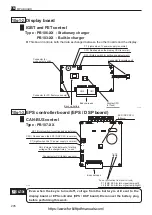
Page 211: ...trols the traction motor and the hydraulic motor CAN BUS control 5 77 77 7 7 7 759 3 3 39 1 2 1 1 759 1 1 1 1 1 1 1 1 1 1 CU harness Fuse protection from short circuit F1 FMC 1 0A for laser pointer F2...

Page 212: ...EPS DSP CPU E8xxxx Fuse protection from short circuit F1 FMC 2 0A for turn signal lamp Left F2 FMC 2 0A for turn signal lamp Right Body harness Connector for PC factory use only RS1 Rotary switch for...

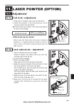
Page 213: ...ser optical axis adjustment Adjustment position Within 1 0 degree of the fork leveling position 1 Park the forklift truck face to the pallet Distance between the pallet and the tip of the fork should...

Page 214: ...13 7 FB14P 400 500 210 290 1710 35 50 5 10 13 7 FB15P 400 500 210 290 1710 35 50 5 10 13 7 FB18P 400 500 250 330 1725 35 50 5 10 15 7 FB20P 400 500 250 330 1950 35 50 5 10 15 7 FB25P 400 500 250 330 2...

Page 215: ...only 3 For adjustment replacement removal installation R R I etc see the respective group pages 4 Unit of work hours The work hours are based on decimal system For example 0 5 30 minutes 1 0 1 hour 5...

Page 216: ...ver 7 0 1 0 1 0 1 Counter weight R R I Control unit 0 5 0 5 0 5 Counter weight with Control unit 0 5 0 5 0 5 Monthly inspection Retightening all fitting bolts 0 2 0 2 0 2 Seat R R I Seat ass y 0 2 0 2...

Page 217: ...oving Wheel 0 1 0 1 0 1 Stud bolt 1 piece after removing Drive shaft 0 1 0 1 0 1 Monthly inspection Two pieces rim bolt and hub bolt nut damage and looseness 0 1 0 1 0 1 Air pressure crack damage wear...

Page 218: ...Wheel 0 2 0 2 0 2 Taper roller bearing one side after removing Hub 0 2 0 2 0 2 Oil seal wheel hub 1 piece after removing King pin 0 1 0 1 0 1 Hub bolt 1 piece after removing Hub 0 1 0 1 0 1 Fill greas...

Page 219: ...looseness and dropped off 0 1 0 1 0 1 Steering linkage R R I Horn contact Horn cap Spring 0 1 0 1 0 1 Pitman arm 0 3 0 3 0 3 Drag link 0 3 0 3 0 3 Rod end 1 piece after removing Drag link 0 1 0 1 0 1...

Page 220: ...1 0 1 0 1 Monthly inspection Entrained air oil leakage damage aging bolt looseness and interference with wheel 0 1 0 1 0 1 Parking brake R R I Microswitch parking brake 0 3 0 3 0 3 Parking lever comp...

Page 221: ...4 0 4 Seal kit 1 set after removing Cylinder 0 3 0 3 0 3 Yearly inspection Operation oil leakage dent crack deflection scratch and fitting bolt looseness 0 1 0 1 0 1 Drift of lowering mm 10min 0 2 0 2...

Page 222: ...in 0 2 0 2 0 2 Tilt cylinder R R I Tilt cylinder ass y 1 piece 0 3 0 3 0 3 Tilt cylinder rod end after removing Cylinder 0 1 0 1 0 1 Rod end bushing after removing Cylinder 0 2 0 2 0 2 Cylinder end co...

Page 223: ...ion rubber 0 1 0 1 0 1 Stopper bracket 0 1 0 1 0 1 Adjust Mast roller adjustment Outer mast inner mast 0 4 0 4 0 4 Back shoe 0 1 0 1 0 1 Lift bracket R R I Lift bracket ass y 0 4 0 4 0 4 Backrest 0 2...

Page 224: ...5 Cover 0 1 0 1 0 1 Clean check Traction motor ass y 0 6 0 6 0 6 Monthly inspection Unusual sound and unusual smell during motor rotation 0 1 0 1 0 1 Yearly inspection Bolt looseness fitting bolt loos...

Page 225: ...4 Carbon brush all 0 4 0 4 0 4 Clean check EPS motor ass y 0 5 0 5 0 5 Repair Grinding commutator and under cutting 0 5 0 5 0 5 Monthly inspection EPS motor unusual noise unusual smell 0 1 0 1 0 1 EPS...

Page 226: ...l hydraulic 0 4 0 4 0 4 Fan comp 1 piece Add 0 3Hrs every time 1 piece is added 0 5 0 5 0 5 Confirmation Travelling speed lift speed plugging distance 0 5 0 5 0 5 Monthly inspection Looseness in termi...

Page 227: ...Indicator panel R R I Indicator panel cover 0 4 0 4 0 4 LCD display unit 0 3 0 3 0 3 Turn signal lamp switch 0 3 0 3 0 3 Sheet switch comp 0 3 0 3 0 3 Display board 0 3 0 3 0 3 Monthly inspection Tur...

Page 228: ...tion Lightning system operation and mounting condition Direction indicator operation and mounting condition Display board and instruments damage and mounting condition Operation water infiltration 0 1...

Page 229: ...age and electrolyte leakage Temperature and specific gravity after charging Max Min Battery plug and cable damage and looseness 0 1 0 1 0 1 Yearly inspection Each cell voltage Max Min 0 1 0 1 0 1 Elec...

Page 230: ...Reproduction prohibited First printing Dec 2003 Second edition Sep 2008 Issued by Nippon Yusoki Co Ltd Edited by Overseas division Nippon Yusoki Co Ltd https www forkliftpdfmanuals com...

Reviews: