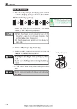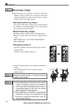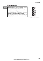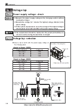
205
10e
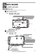
MPU BOARD
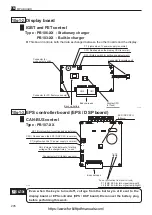
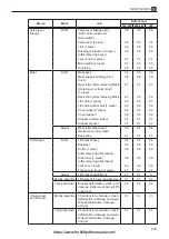
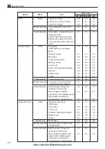
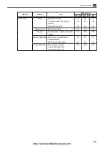
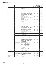
10g-1-2. Display board
10g-1-3. EPS controller board (EPS / DSP board)
0 1 2
3
4
5 6
7 8
9 A
B
C
D
E F
CN2
CN1
Back up battery
Connector for
mode select switch
P7 (Lights when 7V power supply is normal)
CPU (flashes when the display CPU is normal.)
RS1 (Rotary switch for setting and adjustment)
Connector for display unit
Body harness
Display CPU
(L11xxx)
Connector for PC (factory use only)
CPU
121T243E
l
This board controls both the data exchanged between the other boards and the display.
&38
3
$'-
0 1 2
3
4
5 6
7 8
9 A
B
C
D
E F
CPU
EPS / DSP CPU
(E8xxxx)
Fuse ( protection from short circuit)
F1 (FMC 2.0A for turn signal lamp-Left)
F2 (FMC 2.0A for turn signal lamp-Right)
Body harness
Connector for PC (factory use only)
RS1 (Rotary switch for setting and adjustment)
CPU ( Flashes when the EPS / DSP CPU is normal.)
P7 (Lights when the 7V power supply is normal.)
ADJ (Volume for adjustment of starting
voltage of the charger timer) * no use
F1
F2
221T205E
CAUTION
Even when the key is turned off, voltage from the battery is still sent to the
display board or EPS controller (EPS / DSP board). Disconnect the battery plug
before performing this work.
IGBT and FET control
CAN-BUS control
Type : PB106-XX : Stationary charger
PB103-XX : Built-in charger
Type : PB107-XX
https://www.forkliftpdfmanuals.com/


