


Upgrading Your System 4-23
12.
Reattach the retention arm as follows.
Align the end of the retention arm with a single alignment dot to the left
and the end with the two dots to the right. The dots should match
corresponding dots on the cartridge or terminator board.
Push the left end of the retention arm into its slot on the on the left side
of the retention module.
Turn the retention arm to the right and snap it into place on the right side
of the retention module.
13.
Install the required VRM modules (single processor systems come with two
VRM modules installed in VRM sockets 1 and 2). As you add processors,
you need to install additional VRM modules.
For a second processor, install a VRM module in socket 3 (for a total of
three VRM modules for two processors).
For a third processor, install a VRM module in sockets 4 and 5 (for a
total of five VRM modules for three processors).
For a fourth processor, install a VRM module in socket 6 (for a total of
six VRM modules for four processors).
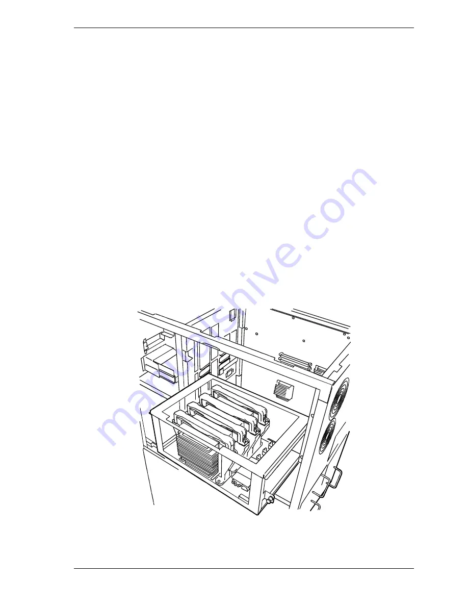
14.
Hold the CPU backboard firmly and mount it in the server (see Figure 4-17).
Align both right and left frames of the CPU backboard with the guide
rails in the server.
Figure 4-17. Installing the CPU Backboard
Summary of Contents for HV8600
Page 1: ... U s e r s G u i d e Server HV8600 ...
Page 2: ...xxx ...
Page 3: ... U s e r s G u i d e Server HV8600 ...
Page 49: ...Setting Up Your System 2 7 Figure 2 2 Connecting the AC Power Cord ...
Page 146: ...5 26 Problem Solving 1041 1040 1042 1043 Power Units ...
Page 152: ...5 32 Problem Solving ...
Page 153: ...A System Cabling Before You Begin Static Precautions RAID and SCSI Bus Configuration ...
Page 158: ...A 6 System Cabling ...
Page 159: ...B Memory Configurations Memory DIMM Configurations ...
Page 162: ...B 4 Memory Configurations ...
Page 184: ...C 22 Management Application Workstation ...
Page 194: ...10 Glossary ...
Page 198: ...4 Equipment Log ...
Page 202: ...Index 4 ...
Page 203: ...xx ...
Page 204: ... 456 01505 000 ...


