


Upgrading Your System 4-41
A
B
C
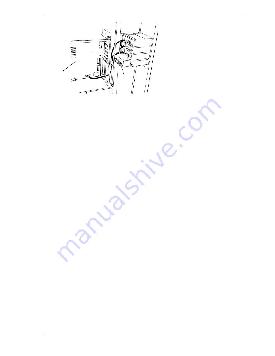
A System I/O board
B Data cable
C Power able
Figure 4-34. Installing Device Cables
Removing a 5 1/4-Inch Device or 3 1/2-Inch Diskette Drive
Remove a 5 1/4-inch device or a 3 1/2-inch diskette drive as follows.
1.
Power off the system. Remove the top panel, left front door, and the left side
panel as described earlier in this chapter.
2.
Disconnect the signal and power cables from the back of the drive
(see Figure 4-34).
3.
Remove the two screws securing the device to the front of the chassis
(see Figure 4-32).
4.
Slide the drive out the front of the bay, and place on an antistatic surface.
5.
Remove and save the side rails and screws (see Figure 4-31).
6.
Place the drive in an antistatic wrapper.
7.
Cover an empty bay by installing a blank panel tray in the bay (see
Figure 4-29).
8.
Reinstall the top panel, left front door, and the left side panel. Power on the
system.
9.
Remove the drive serial number from the equipment log.
Summary of Contents for HV8600
Page 1: ... U s e r s G u i d e Server HV8600 ...
Page 2: ...xxx ...
Page 3: ... U s e r s G u i d e Server HV8600 ...
Page 49: ...Setting Up Your System 2 7 Figure 2 2 Connecting the AC Power Cord ...
Page 146: ...5 26 Problem Solving 1041 1040 1042 1043 Power Units ...
Page 152: ...5 32 Problem Solving ...
Page 153: ...A System Cabling Before You Begin Static Precautions RAID and SCSI Bus Configuration ...
Page 158: ...A 6 System Cabling ...
Page 159: ...B Memory Configurations Memory DIMM Configurations ...
Page 162: ...B 4 Memory Configurations ...
Page 184: ...C 22 Management Application Workstation ...
Page 194: ...10 Glossary ...
Page 198: ...4 Equipment Log ...
Page 202: ...Index 4 ...
Page 203: ...xx ...
Page 204: ... 456 01505 000 ...


