WWW.NNC.IR
3 - 45
3. SIGNALS AND WIRING
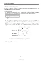
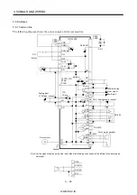
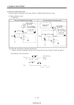
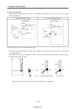
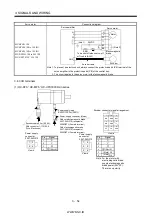
(b) Differential line driver system
1) Interface
Max. output current: 35mA
LA
(LB, LZ)
LAR
(LBR, LZR)
LG
SD
LA
(LB, LZ)
LAR
(LBR, LZR)
SD
Servo amplifier
Servo amplifier
Am26LS32 or equivalent
High-speed photocoupler
150
100
2) Output pulse
Servo motor CCW rotation
LA
LAR
LB
LBR
LZ
LZR
T
/2
400 s or more
OP
The time cycle (T) is determined by
the setting of the parameter No. 27 and 54.
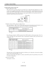
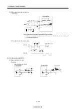
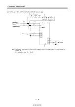
(5) Analog input
Input impedance 10 to 12k
Upper limit setting 2k
15VDC
P15R
VC‚ etc
LG
SD
2k
Servo amplifier
Approx.
10k
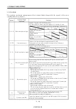
(6) Analog output
Output voltage 10V
Max.1mA
Max. output current
Resolution : 10bit
MO1
(MO2)
LG
SD
A
Servo amplifier
Reading in one or
both directions
1mA meter
10k
Summary of Contents for MR-J2S-*A
Page 13: ...WWW NNC IR A 12 MEMO ...
Page 117: ...WWW NNC IR 3 70 3 SIGNALS AND WIRING MEMO ...
Page 185: ...WWW NNC IR 7 12 7 GENERAL GAIN ADJUSTMENT MEMO ...
Page 195: ...WWW NNC IR 8 10 8 SPECIAL ADJUSTMENT FUNCTIONS MEMO ...
Page 197: ...WWW NNC IR 9 2 9 INSPECTION MEMO ...
Page 221: ...WWW NNC IR 11 10 11 OUTLINE DIMENSION DRAWINGS MEMO ...
Page 293: ...WWW NNC IR 13 64 13 OPTIONS AND AUXILIARY EQUIPMENT MEMO ...
Page 321: ...WWW NNC IR 14 28 14 COMMUNICATION FUNCTIONS MEMO ...
Page 389: ...WWW NNC IR 15 68 15 ABSOLUTE POSITION DETECTION SYSTEM MEMO ...


