WWW.NNC.IR
13 - 53
13. OPTIONS AND AUXILIARY EQUIPMENT
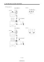
(b) Surge suppressor
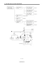
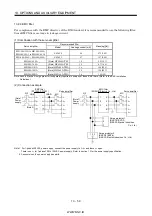
The recommended surge suppressor for installation to an AC relay, AC valve, AC electromagnetic
brake or the like near the servo amplifier is shown below. Use this product or equivalent.
Relay
This distance should be short
(within 20cm(0.79 in.)).
Surge suppressor
MC
Surge suppressor
Surge suppressor
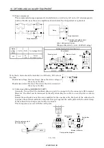
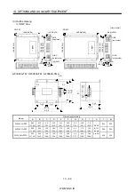
(Ex.) 972A.2003 50411
(Matsuo Electric Co.,Ltd. 200VAC rating)
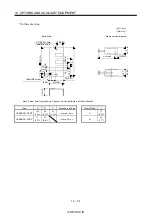
Outline drawing [Unit: mm] ([Unit: in.])
Rated
voltage
AC[V]
C [ F]
R [ ]
Test voltage AC[V]
200
0.5
50
(1W)
Across
T-C 1000(1 to 5s)
Blue vinyl cord
Red vinyl cord
Vinyl sheath
200(7.87)
or more
200(7.87)
or more
6(0.24)
31(1.22)
10(0.39)or less
10(0.39)or less
15 1(0.59 0.04)
48 1.5
(1.89 0.06)
10 3
(0.39
0.12)
10 3
(0.39
0.12)
4(0.16)
18 1.5
(0.71 0.06)
Note that a diode should be installed to a DC relay, DC valve or
the like.
Maximum voltage: Not less than 4 times the drive voltage of
the relay or the like
Maximum current: Not less than twice the drive current of
the relay or the like
Diode
RA
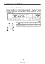
(c) Cable clamp fitting (AERSBAN -SET)
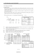
Generally, the earth of the shielded cable may only be connected to the connector's SD terminal.
However, the effect can be increased by directly connecting the cable to an earth plate as shown
below.
Install the earth plate near the servo amplifier for the encoder cable. Peel part of the cable sheath
to expose the external conductor, and press that part against the earth plate with the cable clamp.
If the cable is thin, clamp several cables in a bunch.
The clamp comes as a set with the earth plate.
Strip the cable sheath of
the clamped area.
cutter
cable
Cable clamp
(A,B)
Cable
Earth plate
External conductor
Clamp section diagram
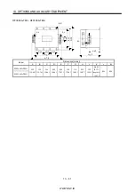
40
(1
.5
7)
Summary of Contents for MR-J2S-*A
Page 13: ...WWW NNC IR A 12 MEMO ...
Page 117: ...WWW NNC IR 3 70 3 SIGNALS AND WIRING MEMO ...
Page 185: ...WWW NNC IR 7 12 7 GENERAL GAIN ADJUSTMENT MEMO ...
Page 195: ...WWW NNC IR 8 10 8 SPECIAL ADJUSTMENT FUNCTIONS MEMO ...
Page 197: ...WWW NNC IR 9 2 9 INSPECTION MEMO ...
Page 221: ...WWW NNC IR 11 10 11 OUTLINE DIMENSION DRAWINGS MEMO ...
Page 293: ...WWW NNC IR 13 64 13 OPTIONS AND AUXILIARY EQUIPMENT MEMO ...
Page 321: ...WWW NNC IR 14 28 14 COMMUNICATION FUNCTIONS MEMO ...
Page 389: ...WWW NNC IR 15 68 15 ABSOLUTE POSITION DETECTION SYSTEM MEMO ...


