WWW.NNC.IR
3 - 27
3. SIGNALS AND WIRING
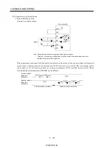
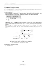
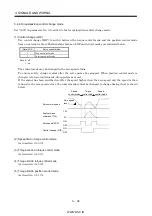
(2) In-position (INP)
PF-SG are connected when the number of droop pulses in the deviation counter falls within the preset
in-position range (parameter No. 5). INP-SG may remain connected when low-speed operation is
performed with a large value set as the in-position range.
Servo-on (SON)
Alarm
Droop pulses
In position (INP)
ON
OFF
Yes
No
In-position range
ON
OFF
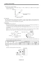
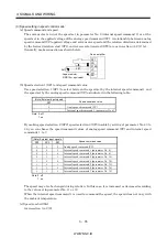
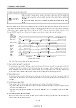
(3) Ready (RD)
Servo-on (SON)
Alarm
Ready (RD)
ON
OFF
Yes
No
80ms or less
10ms or less
10ms or less
ON
OFF
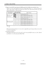
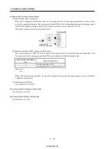
(4) Electronic gear switching
The combination of CM1 and CM2 gives you a choice of four different electronic gear numerators set in
the parameters.
As soon as CM1/CM2 is turned ON or OFF, the molecule of the electronic gear changes. Therefore, if
any shock occurs at this change, use position smoothing (parameter No. 7) to relieve shock.
(Note) External input signal
CM2
CM1
Electronic gear molecule
0
0
Parameter No. 3
0
1
Parameter No. 69
1
0
Parameter No. 70
1
1
Parameter No. 71
Note. 0: off
1: on
Summary of Contents for MR-J2S-*A
Page 13: ...WWW NNC IR A 12 MEMO ...
Page 117: ...WWW NNC IR 3 70 3 SIGNALS AND WIRING MEMO ...
Page 185: ...WWW NNC IR 7 12 7 GENERAL GAIN ADJUSTMENT MEMO ...
Page 195: ...WWW NNC IR 8 10 8 SPECIAL ADJUSTMENT FUNCTIONS MEMO ...
Page 197: ...WWW NNC IR 9 2 9 INSPECTION MEMO ...
Page 221: ...WWW NNC IR 11 10 11 OUTLINE DIMENSION DRAWINGS MEMO ...
Page 293: ...WWW NNC IR 13 64 13 OPTIONS AND AUXILIARY EQUIPMENT MEMO ...
Page 321: ...WWW NNC IR 14 28 14 COMMUNICATION FUNCTIONS MEMO ...
Page 389: ...WWW NNC IR 15 68 15 ABSOLUTE POSITION DETECTION SYSTEM MEMO ...

