WWW.NNC.IR
1 - 5
1. FUNCTIONS AND CONFIGURATION
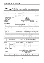
1.3 Servo amplifier standard specifications
Servo Amplifier
MR-J2S-
Item
10A 20A 40A 60A 70A 100A 200A 350A 500A 700A 11KA 15KA 22KA 10A1 20A1 40A1
Voltage/frequency
3-phase 200 to 230VAC,
50/60Hz or 1-phase
230VAC, 50/60Hz
3-phase 200 to 230VAC, 50/60Hz
1-phase 100 to
120VAC
50/60Hz
Permissible voltage fluctuation
3-phase 200 to 230VAC:
170 to 253VAC
1-phase 230VAC: 207 to
253VAC
3-phase 170 to 253VAC
1-phase
85 to 127VAC
Permissible frequency fluctuation
Within 5%
Power supply capacity
Refer to section12.2
Pow
er su
ppl
y
Inrush current
Refer to section 12.5
Control system
Sine-wave PWM control, current control system
Dynamic brake
Built-in
External option
Built-in
Protective functions
Overcurrent shut-off, regenerative overvoltage shut-off, overload shut-off (electronic
thermal relay), servo motor overheat protection, encoder error protection, regenerative
error protection, undervoltage, instantaneous power failure protection, overspeed
protection, excessive error protection
Max. input pulse frequency
500kpps (for differential receiver), 200kpps (for open collector)
Command pulse multiplying factor
Electronic gear A:1 to 65535 131072 B:1 to 65535, 1/50 A/B 500
In-position range setting
0 to 10000 pulse (command pulse unit)
Error excessive
(Note)
2.5 revolutions
Posi
ti
on cont
ro
l m
ode
Torque limit
Set by parameter setting or external analog input (0 to 10VDC/maximum torque)
Speed control range
Analog speed command 1: 2000, internal speed command 1: 5000
Analog speed command input
0 to 10VDC / Rated speed
Speed fluctuation ratio
0.01% or less (load fluctuation 0 to 100%)
0% (power fluctuation 10%)
0.2% or less (ambient temperature 25
10
(
59 to 95
)
),
when using analog speed command
S
pe
ed
co
nt
ro
l mo
de
Torque limit
Set by parameter setting or external analog input (0 to 10VDC/maximum torque)
Analog torque command input
0 to 8VDC / Maximum torque (input impedance 10 to 12k )
Torque
control
mode
Speed limit
Set by parameter setting or external analog input (0 to 10VDC/Rated speed)
Structure
Self-cooled, open (IP00)
Force-cooling, open (IP00)
Self-cooled,
open(IP00)
[ ]
0 to 55 (non-freezing)
In operation
[ ]
32 to 131 (non-freezing)
[ ]
20 to 65 (non-freezing)
Ambient
temperature
In storage
[ ]
4 to 149 (non-freezing)
In operation
Ambient
humidity
In storage
90%RH or less (non-condensing)
Ambient
Indoors (no direct sunlight)
Free from corrosive gas, flammable gas, oil mist, dust and dirt
Altitude
Max. 1000m (3280ft) above sea level
5.9 [m/s
2
] or less
En
vi
ro
nm
en
t
Vibration
19.4 [ft/s
2
] or less
[kg] 0.7 0.7 1.1 1.1 1.7 1.7 2.0 2.0 4.9
15
16
16
20
0.7 0.7 1.1
Mass
[lb] 1.5 1.5 2.4 2.4 3.75 3.75 4.4 4.4 10.8 33.1 35.3 35.3 44.1 1.5 1.5 2.4
Note. The error excessive detection for 2.5 revolutions is available only when the servo amplifier of software version B0 or later is
used. When the software version is earlier than B0, the error excessive detection level of that servo amplifier is 10 revolutions.
Summary of Contents for MR-J2S-*A
Page 13: ...WWW NNC IR A 12 MEMO ...
Page 117: ...WWW NNC IR 3 70 3 SIGNALS AND WIRING MEMO ...
Page 185: ...WWW NNC IR 7 12 7 GENERAL GAIN ADJUSTMENT MEMO ...
Page 195: ...WWW NNC IR 8 10 8 SPECIAL ADJUSTMENT FUNCTIONS MEMO ...
Page 197: ...WWW NNC IR 9 2 9 INSPECTION MEMO ...
Page 221: ...WWW NNC IR 11 10 11 OUTLINE DIMENSION DRAWINGS MEMO ...
Page 293: ...WWW NNC IR 13 64 13 OPTIONS AND AUXILIARY EQUIPMENT MEMO ...
Page 321: ...WWW NNC IR 14 28 14 COMMUNICATION FUNCTIONS MEMO ...
Page 389: ...WWW NNC IR 15 68 15 ABSOLUTE POSITION DETECTION SYSTEM MEMO ...

