WWW.NNC.IR
13 - 19
13. OPTIONS AND AUXILIARY EQUIPMENT
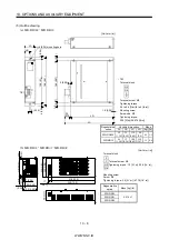
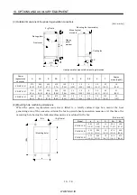
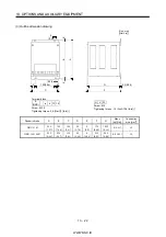
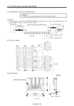
(3) Outside dimensions of the power regeneration converters
[Unit : mm(in)]
AA
A
C
F
K
EE
BA
B
E
D
2- D hole
Rating plate
Front cover
Display
panel
window
Mounting foot (removable)
Mounting foot
movable
Cooling fan
Heat generation area outside mounting dimension
Power
regeneration
converter
A
AA
B
BA
C
D
E
EE
K
F
Approx.
mass [kg(Ib)]
FR-RC-15K
270
(10.6)
200
(7.87)
450
(17.7)
432
(17.0)
195
(7.68)
10
(0.39)
10
(0.39)
8
(0.32)
3.2
(0.13)
87
(3.43)
19
(41.9)
FR-RC-30K
340
(13.4)
270
(10.6)
600
(23.6)
582
(22.9)
195
(7.68)
10
(0.39)
10
(0.39)
8
(0.32)
3.2
(0.13)
90
(3.54)
31
(68.3)
FR-RC-55K
480
(18.9)
410
(16.1)
700
(27.6)
670
(26.4)
250
(9.84)
12
(0.47)
15
(0.59)
15
(0.59)
3.2
(0.13)
135
(5.32)
55
(121)
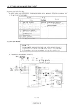
(4) Mounting hole machining dimensions
When the power regeneration converter is fitted to a totally enclosed type box, mount the heat
generating area of the converter outside the box to provide heat generation measures. At this time, the
mounting hole having the following dimensions is machined in the box.
[Unit : mm(in)]
Model
a
b
D
AA
BA
FR-RC-15K
260
(10.2)
412
(16.2)
10
(0.39)
200
(7.87)
432
(17.0)
FR-RC-30K
330
(13.0)
562
(22.1)
10
(0.39)
270
(10.6)
582
(22.9)
FR-RC-55K
470
(18.5)
642
(25.3)
12
(0.47)
410
(16.1)
670
(26.4)
(AA)
(B
A)
b
a
(2- D hole)
(Mounting hole)
Summary of Contents for MR-J2S-*A
Page 13: ...WWW NNC IR A 12 MEMO ...
Page 117: ...WWW NNC IR 3 70 3 SIGNALS AND WIRING MEMO ...
Page 185: ...WWW NNC IR 7 12 7 GENERAL GAIN ADJUSTMENT MEMO ...
Page 195: ...WWW NNC IR 8 10 8 SPECIAL ADJUSTMENT FUNCTIONS MEMO ...
Page 197: ...WWW NNC IR 9 2 9 INSPECTION MEMO ...
Page 221: ...WWW NNC IR 11 10 11 OUTLINE DIMENSION DRAWINGS MEMO ...
Page 293: ...WWW NNC IR 13 64 13 OPTIONS AND AUXILIARY EQUIPMENT MEMO ...
Page 321: ...WWW NNC IR 14 28 14 COMMUNICATION FUNCTIONS MEMO ...
Page 389: ...WWW NNC IR 15 68 15 ABSOLUTE POSITION DETECTION SYSTEM MEMO ...


