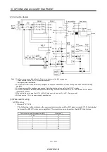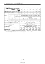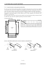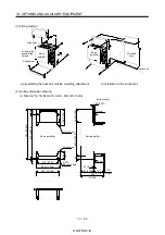
WWW.NNC.IR
13 - 47
13. OPTIONS AND AUXILIARY EQUIPMENT
13.2.2 No-fuse breakers, fuses, magnetic contactors
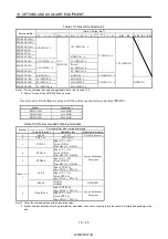
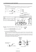
Always use one no-fuse breaker and one magnetic contactor with one servo amplifier. When using a fuse
instead of the no-fuse breaker, use the one having the specifications given in this section.
Fuse
Servo amplifier
No-fuse breaker
Class
Current[A] Voltage AC [V]
Magnetic contactor
MR-J2S-10A(1)
30A frame 5A
K5
10
MR-J2S-20A
30A frame 5A
K5
10
MR-J2S-40A 20A1 30A frame 10A
K5
15
MR-J2S-60A 40A1 30A frame 15A
K5
20
MR-J2S-70A
30A frame 15A
K5
20
MR-J2S-100A
30A frame 15A
K5
25
S-N10
MR-J2S-200A
30A frame 20A
K5
40
250
S-N18
MR-J2S-350A
30A frame 30A
K5
70
S-N20
MR-J2S-500A
50A frame 50A
K5
125
S-N35
MR-J2S-700A
100A frame 75A
K5
150
S-N50
MR-J2S-11KA
100A frame 100A
K5
200
S-N65
MR-J2S-15KA
225A frame 125A
K5
250
S-N95
MR-J2S-22KA
225A frame 175A
K5
350
S-N25
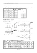
13.2.3 Power factor improving reactors
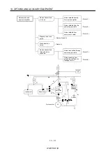
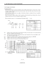
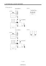
The input power factor is improved to be about 90%. For use with a 1-phase power supply, it may be
slightly lower than 90%.
3-phase
200 to 230VAC
NFB
FR-BAL
R
S
T
X
Y
Z
L
1
L
2
L
3
MC
1-phase
230VAC
NFB
FR-BAL
R
S
T
X
Y
Z
L
1
L
2
L
3
MC
1-phase
100 to120VAC
NFB
FR-BAL
R
S
T
X
Y
Z
L
1
L
2
MC
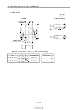
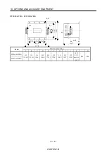
W
W1
C
RX S Y T Z
H
5
D1
Installation screw
D
5
[Unit : mm]
(Note)
Servo amplifier
MR-J2S- A
Servo amplifier
MR-J2S- A
Servo amplifier
MR-J2S- A1
Note. For the 1-phase 230V power supply, Connect the power supply to L
1
, L
2
and leave L
3
open.
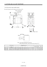
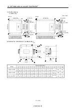
Dimensions [mm (in) ]
Servo amplifier
Model
W
W1
H
D
D1
C
Mounting
screw size
Terminal
screw size
Mass
[kg (lb)]
MR-J2S-10A(1)/20A
FR-BAL-0.4K
135 (5.31) 120 (4.72) 115 (4.53) 59 (2.32) 45
0
-2.5
(1.77
0
-0.098
) 7.5 (0.29)
M4
M3.5
2.0 (4.4)
MR-J2S-40A/20A1
FR-BAL-0.75K 135 (5.31) 120 (4.72) 115 (4.53) 69 (2.72) 57
0
-2.5
(2.24
0
-0.098
) 7.5 (0.29)
M4
M3.5
2.8 (6.17)
MR-J2S-60A/70A/40A1 FR-BAL-1.5K
160 (6.30) 145 (5.71) 140 (5.51) 71 (2.79) 55
0
-2.5
(2.17
0
-0.098
) 7.5 (0.29)
M4
M3.5
3.7 (8.16)
MR-J2S-100A
FR-BAL-2.2K
160 (6.30) 145 (5.71) 140 (5.51) 91 (3.58) 75
0
-2.5
(2.95
0
-0.098
) 7.5 (0.29)
M4
M3.5
5.6 (12.35)
MR-J2S-200A
FR-BAL-3.7K
220 (8.66) 200 (7.87) 192 (7.56) 90 (3.54) 70
0
-2.5
(2.76
0
-0.098
)
10 (0.39)
M5
M4
8.5 (18.74)
MR-J2S-350A
FR-BAL-7.5K
220 (8.66) 200 (7.87) 194 (7.64) 120 (4.72) 100
0
-2.5
(3.94
0
-0.098
) 10 (0.39)
M5
M5
14.5 (32.0)
MR-J2S-500A
FR-BAL-11K
280 (11.02) 255 (10.04) 220 (8.66) 135 (5.31) 100
0
-2.5
(3.94
0
-0.098
) 12.5 (0.49)
M6
M6
19 (41.9)
MR-J2S-700A/11KA
FR-BAL-15K
295 (11.61) 270 (10.62) 275 (10.83) 133 (5.24) 110
0
-2.5
(4.33
0
-0.098
) 12.5 (0.49)
M6
M6
27 (59.5)
MR-J2S-15KA
FR-BAL-22K
290 (11.41) 240 (9.75) 301 (11.85) 199 (7.84) 170 5 (6.69 0.2) 25 (0.98)
M8
M8
35 (77.16)
MR-J2S-22KA
FR-BAL-30K
290 (11.41) 240 (9.75) 301 (11.85) 219 (8.62) 190 5 (7.48 0.2) 25 (0.98)
M8
M8
43 (94.79)
Summary of Contents for MR-J2S-*A
Page 13: ...WWW NNC IR A 12 MEMO ...
Page 117: ...WWW NNC IR 3 70 3 SIGNALS AND WIRING MEMO ...
Page 185: ...WWW NNC IR 7 12 7 GENERAL GAIN ADJUSTMENT MEMO ...
Page 195: ...WWW NNC IR 8 10 8 SPECIAL ADJUSTMENT FUNCTIONS MEMO ...
Page 197: ...WWW NNC IR 9 2 9 INSPECTION MEMO ...
Page 221: ...WWW NNC IR 11 10 11 OUTLINE DIMENSION DRAWINGS MEMO ...
Page 293: ...WWW NNC IR 13 64 13 OPTIONS AND AUXILIARY EQUIPMENT MEMO ...
Page 321: ...WWW NNC IR 14 28 14 COMMUNICATION FUNCTIONS MEMO ...
Page 389: ...WWW NNC IR 15 68 15 ABSOLUTE POSITION DETECTION SYSTEM MEMO ...

