WWW.NNC.IR
15 - 17
15. ABSOLUTE POSITION DETECTION SYSTEM
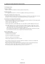
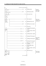
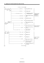
(4) At the time of emergency stop reset
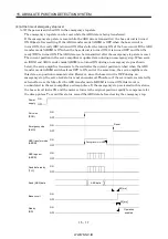
(a) If the power is switched ON in the emergency stop state
The emergency stop state can be reset while the ABS data is being transferred.
If the emergency stop state is reset while the ABS data is transmitted, the base circuit is turned
ON 80[ms] after resetting. If the ABS transfer mode (ABSM) is OFF when the base circuit is
turned ON, the ready (RD) is turned ON 20[ms] after the turning ON of the base circuit. If the ABS
transfer mode (ABSM) is ON when the base circuit is turned ON, it is turned OFF and then the
ready (RD) is turned ON. The ABS data can be transmitted after the emergency stop state is reset.
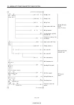
The current position in the servo amplifier is updated even during an emergency stop. When servo-
on (SON) and ABS transfer mode (ABSM) are turned ON during an emergency stop as shown
below, the servo amplifier transmits to the controller the current position latched when the ABS
transfer mode (ABSM) switches from OFF to ON, and at the same time, the servo amplifier sets
this data as a position command value. However, since the base circuit is OFF during an
emergency stop, the servo-lock status is not encountered. Therefore, if the servo motor is rotated by
external force or the like after the ABS transfer mode (ABSM) is turned ON, this travel is
accumulated in the servo amplifier as droop pulses. If the emergency stop is cleared in this status,
the base circuit turns ON and the motor returns to the original position rapidly to compensate for
the droop pulses. To avoid this status, reread the ABS data before clearing the emergency stop.
OFF
ON
OFF
ON
OFF
ON
OFF
ON
OFF
ON
OFF
ON
OFF
ON
80[ms]
OFF
ON
20[ms]
Power
supply
Servo-on
(SON)
Emergency stop
(EMG)
ABS transfer mode
(ABSM)
ABS request
(ABSR)
Send data ready
(TLC)
Send (ABS) data
Base circuit
Ready
(RD)
Reset
During transfer of ABS
ABS data
Operation
enabled
Summary of Contents for MR-J2S-*A
Page 13: ...WWW NNC IR A 12 MEMO ...
Page 117: ...WWW NNC IR 3 70 3 SIGNALS AND WIRING MEMO ...
Page 185: ...WWW NNC IR 7 12 7 GENERAL GAIN ADJUSTMENT MEMO ...
Page 195: ...WWW NNC IR 8 10 8 SPECIAL ADJUSTMENT FUNCTIONS MEMO ...
Page 197: ...WWW NNC IR 9 2 9 INSPECTION MEMO ...
Page 221: ...WWW NNC IR 11 10 11 OUTLINE DIMENSION DRAWINGS MEMO ...
Page 293: ...WWW NNC IR 13 64 13 OPTIONS AND AUXILIARY EQUIPMENT MEMO ...
Page 321: ...WWW NNC IR 14 28 14 COMMUNICATION FUNCTIONS MEMO ...
Page 389: ...WWW NNC IR 15 68 15 ABSOLUTE POSITION DETECTION SYSTEM MEMO ...

