WWW.NNC.IR
15 - 1
15. ABSOLUTE POSITION DETECTION SYSTEM
15. ABSOLUTE POSITION DETECTION SYSTEM
CAUTION
If an absolute position erase alarm (AL.25) or an absolute position counter warning
(AL.E3) has occurred, always perform home position setting again. Not doing so
may cause unexpected operation.
POINT
When configuring an absolute position detection system using the QD75P/D
PLC, refer to the Type QD75P/QD75D Positioning Module User's Manual
(SH (NA) 080058).
15.1 Outline
15.1.1 Features
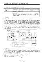
For normal operation, as shown below, the encoder consists of a detector designed to detect a position
within one revolution and a cumulative revolution counter designed to detect the number of revolutions.
The absolute position detection system always detects the absolute position of the machine and keeps it
battery-backed, independently of whether the general-purpose programmable controller power is on or
off. Therefore, once the home position is defined at the time of machine installation, home position return
is not needed when power is switched on thereafter.
If a power failure or a fault occurs, restoration is easy.
Also, the absolute position data, which is battery-backed by the super capacitor in the encoder, can be
retained within the specified period (cumulative revolution counter value retaining time) if the cable is
unplugged or broken.
LSO
1XO
MR-BAT
CPU
General purpose programmable
controller
Servo amplifier
Pulse train
(command)
Changi
n
g t
h
e
curre
nt
posi
tio
n
dat
a
Positioning module
I/O module
Current
position
data
Input
Output
Home position data
EEPROM memory
Backed up in the
case of power failure
Current
position
data
Detecting the
number of
revolutions
LS
1X
Detecting the
position within
one revolution
P
osit
ion cont
ro
l
S
peed c
on
trol
Servo motor
1 pulse/rev Accumulative
revolution counter
Super capacitor
Within-one-revolution counter
(Position detector)
High speed serial
communication
Battery
15.1.2 Restrictions
The absolute position detection system cannot be configured under the following conditions. Test
operation cannot be performed in the absolute position detection system, either. To perform test
operation, choose incremental in parameter No.1.
(1) Speed control mode, torque control mode.
(2) Control switch-over mode (position/speed, speed/torque, torque/position).
(3) Stroke-less coordinate system, e.g. rotary shaft, infinitely long positioning.
(4) Changing of electronic gear after home position setting.
(5) Use of alarm code output.
Summary of Contents for MR-J2S-*A
Page 13: ...WWW NNC IR A 12 MEMO ...
Page 117: ...WWW NNC IR 3 70 3 SIGNALS AND WIRING MEMO ...
Page 185: ...WWW NNC IR 7 12 7 GENERAL GAIN ADJUSTMENT MEMO ...
Page 195: ...WWW NNC IR 8 10 8 SPECIAL ADJUSTMENT FUNCTIONS MEMO ...
Page 197: ...WWW NNC IR 9 2 9 INSPECTION MEMO ...
Page 221: ...WWW NNC IR 11 10 11 OUTLINE DIMENSION DRAWINGS MEMO ...
Page 293: ...WWW NNC IR 13 64 13 OPTIONS AND AUXILIARY EQUIPMENT MEMO ...
Page 321: ...WWW NNC IR 14 28 14 COMMUNICATION FUNCTIONS MEMO ...
Page 389: ...WWW NNC IR 15 68 15 ABSOLUTE POSITION DETECTION SYSTEM MEMO ...

