WWW.NNC.IR
15 - 24
15. ABSOLUTE POSITION DETECTION SYSTEM
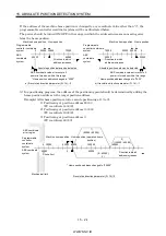
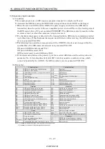
If the address of the machine home position is changed to any coordinate value other than "0", the
programmable controller coordinate system will be as illustrated below.
The power should be turned ON/OFF in the range in which the address increases on moving away
from the home position.
0
20000
20000 30000
70000
50000
0
20000
30000
70000
50000
20000
0
0
Machine home position Home position
Programmable
controller coordinate
system
ABS
coordinate
system
a) If revolution direction parameter (Pr. 14) 0
Programmable
controller coordinate
system
ABS
coordinate
system
Direction in which
address increases
Direction in which
address increases
Machine home position Home position
Absolute position data can be detected
Absolute position data can be detected
ABS coordinate value error occurs if
power is turned on within this range
ABS coordinate value error occurs if
power is turned on within this range
* Home position address changed to "2000"
* Home position address changed to "2000"
b) If revolution direction parameter (Pr. 14) 1
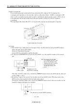
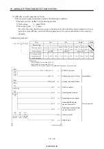
(c) In a positioning program, the address of the positioning point should be determined by adding the
home position address to the target position address.
Example) After home position return, execute positioning at 1) to 3).
1) Positioning at position address 80000
(PC coordinate 140000)
2) Positioning at position address 130000
(PC coordinate 190000)
3) Positioning at position address 0
(PC coordinate 60000)
0
50000
10000
50000
0
100000
50000
60000
150000
1)
(80000 60000)
2)
(130000 60000)
(0 60000)
3)
ABS coordinate
error region
Programmable
controller
coordinate
system
ABS coordinate
system
Mechanical limit
Machine home position Home position (operation home
Stroke limit
* Home position address changed to "50000"
If revolution direction parameter (Pr. 14) 0
Direction in which
address increases
position)
Summary of Contents for MR-J2S-*A
Page 13: ...WWW NNC IR A 12 MEMO ...
Page 117: ...WWW NNC IR 3 70 3 SIGNALS AND WIRING MEMO ...
Page 185: ...WWW NNC IR 7 12 7 GENERAL GAIN ADJUSTMENT MEMO ...
Page 195: ...WWW NNC IR 8 10 8 SPECIAL ADJUSTMENT FUNCTIONS MEMO ...
Page 197: ...WWW NNC IR 9 2 9 INSPECTION MEMO ...
Page 221: ...WWW NNC IR 11 10 11 OUTLINE DIMENSION DRAWINGS MEMO ...
Page 293: ...WWW NNC IR 13 64 13 OPTIONS AND AUXILIARY EQUIPMENT MEMO ...
Page 321: ...WWW NNC IR 14 28 14 COMMUNICATION FUNCTIONS MEMO ...
Page 389: ...WWW NNC IR 15 68 15 ABSOLUTE POSITION DETECTION SYSTEM MEMO ...

