WWW.NNC.IR
5 - 14
5. PARAMETERS
Class No. Symbol
Name and function
Initial
value
Unit
Setting
range
Control
mode
21
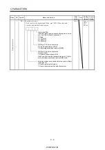
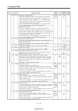
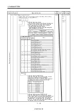
*OP3 Function selection 3 (Command pulse selection)
Used to select the input form of the pulse train input signal.
(Refer to section 3.4.1)
Command pulse train input form
0: Forward/reverse rotation pulse train
1: Signed pulse train
2: A B-phase pulse train
Pulse train logic selection
0: Positive logic
1: Negative logic
0 0
0000
Refer to
Name
and
function
column.
P
22
*OP4
0000
P S
E
xpa
n
si
on
pa
ra
m
et
ers
1
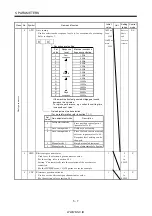
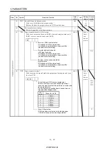
Function selection 4
Used to select stop processing at forward rotation stroke end (LSP)
reverse rotation stroke end (LSN) off and choose VC/VLA voltage
averaging.
How to make a stop when forward
rotation stroke end (LSP) reverse rotation stroke end
(LSN) is valid. (Refer to section 5.2.3)
0: Sudden stop
1: Slow stop
VC/VLA voltage averaging
Used to set the filtering time when the analog speed
command (VC) voltage or analog speed limit (VLA) is
imported.
Set 0 to vary the speed to voltage fluctuation in real
time. Increase the set value to vary the speed slower
to voltage fluctuation.
Set
value
0
Filtering time [ms]
0
1
0.444
2
0.888
3
1.777
4
3.555
0
0
Refer to
Name
and
function
column.
P S T
Summary of Contents for MR-J2S-*A
Page 13: ...WWW NNC IR A 12 MEMO ...
Page 117: ...WWW NNC IR 3 70 3 SIGNALS AND WIRING MEMO ...
Page 185: ...WWW NNC IR 7 12 7 GENERAL GAIN ADJUSTMENT MEMO ...
Page 195: ...WWW NNC IR 8 10 8 SPECIAL ADJUSTMENT FUNCTIONS MEMO ...
Page 197: ...WWW NNC IR 9 2 9 INSPECTION MEMO ...
Page 221: ...WWW NNC IR 11 10 11 OUTLINE DIMENSION DRAWINGS MEMO ...
Page 293: ...WWW NNC IR 13 64 13 OPTIONS AND AUXILIARY EQUIPMENT MEMO ...
Page 321: ...WWW NNC IR 14 28 14 COMMUNICATION FUNCTIONS MEMO ...
Page 389: ...WWW NNC IR 15 68 15 ABSOLUTE POSITION DETECTION SYSTEM MEMO ...


