MIMAKI UJF-605RII Operation Manual Download Page 57

- 2-15 -

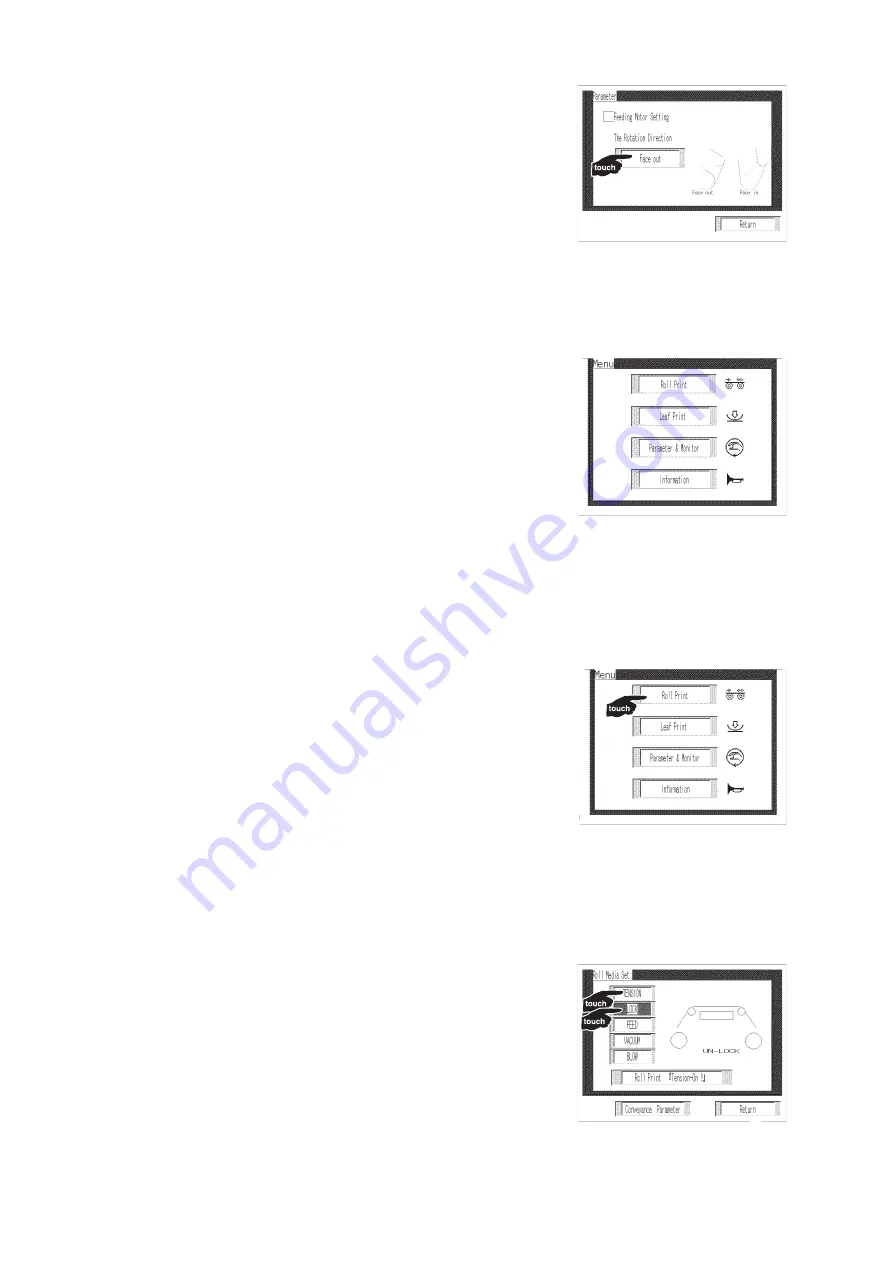
c. Touch the [The rotation direction].

Switch the [Face in] or [Face out] by touching

the panel.

d. Touch the [Return] three times.

Return to the [Menu] screen.

e. Touch the [Roll Print].

f. Touch the [TENSION] and [LOCK].

The roll media turns around.

Make sure of the turning direction.

If a wrong rotation direction is selected, start

from STEP a.

Summary of Contents for UJF-605RII

Page 1: ...gawa Shinagawa ku Tokyo 141 0001 Japan Phone 81 3 5420 8671 Fax 81 3 5420 8687 URL http www mimaki co jp E mail trading mimaki jp Operation Manual D201670 Never look at the UV lamp being lit with your naked eyes or it may cause pain in your eyes or visual impairment ...

Page 2: ...er by yourself Setting up should be conducted by your service engineer or the electric contractor Operation Manual The above manual describes operations of the printer and daily maintenance Read this operation manual carefully and fully understand it to use the printer Daily Care Manual The above manual describes daily maintenance to keep the printer in good condition ...

Page 3: ...MIMAKI BE LIABLE FOR SPE CIAL INCIDNETAL OR CONSEQUENTIAL DAMAGES OR FOR LOSS OF PROFITS OF DEALER OR CUSTOMERS OF ANY PRODUCT Requests This operation manual has been carefully prepared for your easy understanding how ever please do not hesitate to contact a distributor in your district or our office if you have any inquiry Description contained in this operation manual are subject to change witho...

Page 4: ...rom the product Use a power line for the receiver that is not shared with the product FCC Statement USA This equipment has been tested and found to comply with the limits for a Class A digital device pursuant to Part 15 of the FCC Rules These limits are designed to provide reason able protection against harmful interference when the equipment is operated in a commer cial environment This equipment...

Page 5: ...he printer Please read and fully understand this operation manual before putting the printer into service It is also necessary to keep this operation manual on hand Make arrangements to deliver this operation manual to the person in charge of the opera tion of this printer This operation manual has been carefully prepared for your easy understanding how ever please do not hesitate to contact a dis...

Page 6: ...t 1 5 Rear left 1 5 Carriage 1 10 Capping Station 1 10 Flushing Tray 1 11 Head height adjustment rod 1 11 Connecting the Cables 1 12 Connecting the Interface Cable 1 12 IEEE 1394 Interface is Used 1 12 IEEE 1284 Interface is Used 1 12 Connecting the Power Cable 1 13 UV Unit and UV Irradiation Device 1 14 UV Irradiation Device 1 14 About Functions of UV Lamp Status Indicator 1 15 Mode for the UV La...

Page 7: ...ON ORIGIN 2 26 Checking and Solving Nozzle Clogging 2 28 Normal Pattern 2 28 Abnormal Pattern 2 29 Printing an Image from Data 2 30 Starting the Printing Operation 2 30 Printing Repeatedly COPY 2 32 Canceling Printing 2 33 Printing multi editions repeatedly multi editions copy 2 34 Cycle Stop 2 36 Setting a New Ink Cartridge in the Ink Station 2 37 Ink Cartridge Trouble 2 38 Turning the Power off ...

Page 8: ... Turning off the UV Irradiation Device UV LAMP OFF 4 8 Changing the Display Language DISPLAY 4 9 Chapter 5 Maintenance Functions About Maintenance 5 2 Introduction of the Maintenance Functions 5 2 List of Maintenance Functions 5 2 Printing out the Printing Conditions LIST 5 3 When Media Thickness is Changed PRINT ADJUST 5 4 Cleaning the Ink Station Interior STATION CARRIAGE OUT 5 6 If Nozzles are ...

Page 9: ...tion Level 5 26 Displaying the Printer Information INFORMATION 5 32 Prevent the nozzle clogging of spot color SP REFRESH 5 33 Chapter 6 Trouble shooting Before Thinking the Printer is in Failure 6 2 The Printer cannot be Turned on 6 2 The Printer cannot Perform Printing 6 2 WATER NOT READY or UV NOT READY is displayed 6 2 When the Printing Quality is Defective 6 3 Troubles for Which Error Messages...

Page 10: ...fter printing Use of an ultraviolet curing device UV lamp enables curing and fixing of ink after printing Wide printable area The printable area is 600 mm scan x 500 mm feed Printing on the film media It is printable for thin roll film media from with 0 02 to 0 2mm and for leaf film media from with 0 02 to 2 0mm It is printable for a roll film media by automatic transport This printer comes equipp...

Page 11: ...rmation for using the printer Example of Symbols 2 The symbol indicates the case where some phenom enon that requires a CAUTION sign including DANGER and WARNING signs exists A concrete precaution the precaution against an electric shock in the case of the left symbol is shown in the illustration The symbol indicates a prohibited behavior A concrete content of prohibition disassembly is prohibited...

Page 12: ...ry of UN no 3082 and UN class 9 Since the ink is flammable never allow an flame or spark to get near the ink any time When cleaning the ink station and head be sure to wear the supplied goggle and gloves to prevent getting ink your eyes or on your If anyone drinks ink or the washing liquid in mistake get the person to vomit immediately and see a doctor Do not allow him or her to drink vomit Then c...

Page 13: ...ng initiator have toxic consequences to aquatic life Avoid leak into natural water system or sewage containing water Do not disassemble or modify the printer Never disassemble or remodel the main unit of the printer and the ink cartridge Disassembling remodeling any of them will result in electric shocks or failures of the printer Do not use the printer in damp places Avoid using the printer in da...

Page 14: ... the use of a UV lamp not recommended by MIMAKI As the UV lamp is made of glass it should not be dropped hit against anything subjected to excessive force or scratched or it may cause damages to the UV lamp Do not use the UV lamp in an atmosphere where it could catch fire such as contacting gasoline combustible gas spray thinner lacquer powder dust etc In addition do not put paper or cloth near or...

Page 15: ... or mixed soft water with antifreezing liquid gets on the skin immediately wash it off with soap and cool with iced water Then consult a doctor as soon as possible If you swallow the antifreezing liquid or mixed soft water with antifreezing liquid accidentally try to get to vomit and then consult a doctor as soon as possible Before using the antifreezing liquid be sure to read the Material Safety ...

Page 16: ... or our office Front cover Never open the front cover during printing Opening the cover or lever will abort printing Adjusting the level Adjust the level foot and keep the printer in a horizontal position Ink cartridges If the ink cartridge is moved from a cold place to a warm place then use for three hours Open the ink cartridge just before installing it in the printer If it is opened and not ins...

Page 17: ...is smoking or sparking or has an abnormal order turn it OFF immediately and contact MIMAKI CAUTION About UV light Some UV light leaks from the openings for media UV light applied to your skin or your eyes might cause inflammation or skin cancer Thought weak UV light might cause no inflammation repeated exposure to it may lead to chronic disorders Avoid minimize getting UV light on your skin or eye...

Page 18: ...ut become overheated CAUTION A place which receives direct sunlight Do not install printer in any place where it will be subjected to direct sunlight A place where the temperature and humidity fluctuate greatly Use the device under the following operating environment 15 to 30 C 59 to 86 F 35 to 65 Rh A place which receives direct air blowing from air conditioner etc Do not install the printer in a...

Page 19: ... Do not print up to the posterior end of the roll media Leave a margin 1000mm or more from the end It may cause wrinkles Leave a space in RIP between each printing part not to cause wrinkles Otherwise the wrinkles in printing parts and space may cause new wrinkle at next printing part Feeding side Face out Media Vacuum table 1000mm or more Face in Media Vacuum table Face in Face out Feeding side 1...

Page 20: ...cedure and the content of display on the LCD In this manual each setting and messages dis played on the LCD is enclosed in like TYPE 1 PLEASE WAIT etc Display on the LCD LOCAL mode screen Operation In the text of this operation manual the operation are explained with used and indicate JOG The other operation are explained with brackets enclosed as FUNCTION LOCAL mode screen JOG They are used to sh...

Page 21: ...printing Chapter 3 Daily Care This chapter describes the recovery procedure for ink clogging and the cleaning procedure for each section Chapter 4 Various Setting This chapter describes the setting function Chapter 5 Maintenance Functions This chapter describes maintenance procedures including solving nozzle clogging replacing the UV lamp etc Chapter 6 Troubleshooting This chapter describes what t...

Page 22: ... xx ...

Page 23: ...on of the printer Table of Contents Installing the Printer 1 2 Configurations and Functions 1 4 Connecting the Cables 1 12 UV Unit and UV Irradiation Device 1 14 Installing the Ink Cartridges 1 17 Cautions for Handling the Ink Cartridge 1 18 Types of Usable Media 1 19 Menu Mode 1 20 ...

Page 24: ...Height Gross weight UJF 605RII 2340 mm 1920 mm 1560 mm Approx 800 kg 4340 mm 1000 mm or more 1000 mm or more 1000 mm or more 3920 mm 1000 mm or more This unit cannot be installed by customers Its installation should be en trusted to our service personnel or your electrical contractor Be sure to carry out grounding work In order to prevent electrical shocks from occurring carrying out electrical wo...

Page 25: ...re moving the unit wait until the UV lamp is cooled When moving the printer take care not to shake it Be sure to adjust the level feet so that the printer is level after moving it Do not hold the table or the ink cartridges or it may give damage to the printer Raising and Lowering Level Feet Before moving the printer raise the level feet sufficiently so that the printer easily rolls When installin...

Page 26: ...icates the UV lamp status P 1 15 Error UV lamp OFF red cooling orange enabled green 11 Adjustment volume Adjusts the tension for media transport and vacuum blow for media P 1 9 12 Take up unit Rolls up the media 13 Roll set bar Set a paper core in the center and lift the lever up to give driving power to the paper core 14 IEEE1284 connector Bidirectional parallel interface connector 15 IEEE1394 co...

Page 27: ...e driving power to the roll media 3 Roll media cover Covers the carrier path of the roll media 4 Ink station cover Opened to insert the ink cartridges Name Function 1 Feeding unit Rolls down the media 2 Connecter for feeding The power connecter for the feeding unit 3 Main unit power cable Supplies power for the main unit 3 1 4 2 2 1 3 Rear left ...

Page 28: ... remaining amount of each color ink Version screen This displays each versions of Firm Ware Hard Ware and SQ Program Operation Panel The operation panel is touch panel type and used for operation procedure of printing and various operations Menu screen The first screens exits and then this is displayed automatically Touch an item with your finger to move to each screen ...

Page 29: ...ia The sub switch in front of the right printer can operate the same functions as well Roll Print screen This is the LOCAL mode screen for printing roll media information screen The irradiation time of the UV lamp the remaining ink and a printer version are displayed by touching each item Leaf Print screen This is the LOCAL mode screen for printing leaf media ...

Page 30: ...on menu CLEANING Performs head cleaning P 2 29 Functions of the JOG Each of the JOG varies in function according to the time at which it is used Display Displays the printer condition a set item a guidance error etc REMOTE Change the operation mode between the REMOTE mode and the LOCAL mode COPY Repeats printing the printed data P 2 32 JOG They are used to shift the carriage and the media under th...

Page 31: ...es and contents of operations TENSION Drives feeding side motor and operates the tension roller to tense the media toward the feeding motor LOCK Locks the free take up side motor FEED Drives the take up side motor to take up the media VACUUM Adsorbs media and fixes it on the table BLOW Discharges air and lifts up the media which is absorbed and fixed on the table Roll Leaf effective ineffective Ro...

Page 32: ...rriage moves inside of the left maintenance cover on standby Capping Station It is placed inside of the right maintenance cover in front of the printer The capping station consists of ink caps for print head maintenance and a suction nozzle P 3 3 Print heads UV irradiation device Suction nozzle Ink cap ...

Page 33: ...Head height adjustment rod When a media is set on the device for the first time or when a media different in thickness from the current media is set on the device it is necessary to adjust the height of the table If the device is operated without adjusting the head height the heads may get caught on the media causing damage to the heads For the method of head height adjustment see Setting Media P ...

Page 34: ...94 Interface is Used Use an IEEE 1394 interface cable to connect the computer and the printer if your computer has an IEEE1394 interface The RIP used must be applicable to IEEE 1394 Both IEEE 1394 connectors are available The computer is not provided with an IEEE 1394 board contact your nearest RIP provider or MIMAKI sales office IEEE 1284 Interface is Used Use an IEEE 1284 interface cable to conn...

Page 35: ...re required Connecting the power cable by customer is not allowed Be sure to contact your local distributor to call for service to connect the power cable as well as moving installation of the device We should take no responsibility for any troubles caused through the power cable connection by customers without calling for service ...

Page 36: ...ing lit or immediately after it is turned OFF because the UV lamp is hot and dangerous In 2 minutes after turning on the printer this device is enabled to irradiate UV light UV Unit and UV Irradiation Device The UV irradiation device is equipped with a shutter mechanism The shutter is opened automatically only when printing ...

Page 37: ...4 7 Flowchart for the UV indicator UV lamp OFF Press REMOTE key Start TEST DRAW UV lamp preheated Display Indication Preheating completed UV lamp steadily ON Error occurred Turn off UV lamp No operation for 30 minutes UV lamp being cooled Cooling completed Main unit power ON YES YES YES YES YES YES YES YES NO NO NO NO NO NO NO UV lamp OFF Main unit stopped Main unit power OFF Main unit power OFF R...

Page 38: ... been set OFF it is cooled The UV lamp cannot be set ON again and the printer cannot start printing until this light goes off OFF The other 2 modes Error mode ON red 1 Error in UV power 2 UV lamp overheated The UV lamp goes OFF the lamp cooling fan stops and printing with the printer also stops 3 When the UV irradiation device shutter does not work normally OFF Normal Mode for the UV Lamp Status I...

Page 39: ... carry out initial filling P 2 7 Relationships between the Ink Station and the Head Row One color ink is applied to one size nozzle Remember these relationships when checking clogged nozzles of the heads replacing an ink cartridge and filling up inks Black Magenta Cyan Yellow Light Cyan Light Magenta White Black Magenta Cyan Yellow Light Cyan Light Magenta White HEAD Spot color Spot color Front si...

Page 40: ...consume the ink in the ink cartridge once it is opened within six months If an extended period of time has passed after opening the cartridge package printing quality would be poor Store the ink cartridges in a place that is out of reach of children When discarding unused ink cartridges entrust them to an industrial waste disposal contractor clarifying their contents Some components photo initiato...

Page 41: ...in which they are used for 30 minutes or more after unpacking Curling of media Leaf media should be flat or curled downward swelled at the center with the printing surface facing up Media curled upward may not be absorbed to the table When storing media that is easily curled place them on a base or pallet slightly smaller than the media area so that the media will be curled downward during storage...

Page 42: ...inting data the printer printed 5 Touching the FUNCTION to set printing conditions FUNCTION mode FUNCTION mode While the printer is in the LOCAL mode touch the FUNCTION to put the printer into the FUNCTION mode This is the mode in which printing conditions can be set Refer to the chapter 4 Various setting or chapter 5 Maintenance Functions REMOTE mode The printer prints an image from data it recei...

Page 43: ...3 Opening Closing Covers 2 6 Initial Filling of Inks 2 7 Setting Media 2 8 Adjustment of the Table Height TBL HEIGHT 2 22 Setting the Origin and the Print Area 2 24 Checking and Solving Nozzle Clogging 2 28 Printing an Image from Data 2 30 Setting a New Ink Cartridge in the Ink Station 2 37 Ink Cartridge Trouble 2 38 Turning the Power off 2 39 ...

Page 44: ... Data transmission Turning the power off Setting the origin Setting the media Checking the nozzle condition Flow Chart The following shows a series of operations from power on to end of printing For details on each item refer to the reference page P 2 8 P 2 3 P 2 25 P 2 28 P 2 30 P 2 39 ...

Page 45: ... performed If the temperature in the water heater has not reached the predetermined value the message is indicated In this case printing is disabled It is enabled when the error message disappears 2 Select a media type on the Menu screen on the touch panel Touch the Roll Print for roll print When not setting roll media touch the Roll Media Set Refer to Setting Media P 2 8 LOCAL WATER NOT READY ...

Page 46: ...nformation Display the printer information by touching ENTER The following explains the procedure for displaying information in LOCAL mode Even in the REMOTE mode you can display information by touching the ENTER 1 Touch the ENTER in the LOCAL mode and the Ink remaining is displayed 3 Touch the ENTER and the firmware version and command version are dis played Refer to Information in the Mainte nan...

Page 47: ... UV lamp irradiation duration is displayed Refer to Replacing UV Lamp in the Maintenance Functions item for displaying UV lamp irradiation dura tion P 5 17 5 Touch the ENTER the screen returns to the LOCAL mode UV USED TIME 600 h 00m LOCAL ...

Page 48: ...ocedures STEPS 1 When opening a cover during printing the message shown on the right is displayed Printing is stopped 2 The data transmission from the computer is stopped 3 Close the cover 4 Touch the ENTER 5 The carriage starts to move The carriage will carry out a series of action that are the same as those taken after turning on the power to the printer 6 Touch the FUNCTION to display the data ...

Page 49: ...ER 7 Touch the JOG or to select the print head 8 Touch the JOG or to display the print head Which are not filled with ink Put symbol for colors to be filled with no ink 9 Touch the ENTER 10 Touch the ENTER again The print heads are automatically filled with ink 11 Once the ink filling procedure is com pleted the display shows the right mes sage Touch END twice the printer returns to the LOCAL mode...

Page 50: ...2 to 0 2 mm and for leaf media with 0 02 to 2 0 mm Pouched films or tube films are unusable because they cannot be ab sorbed to the table Set the media properly not to cause any wrinkles Otherwise printing does not work well Do not use media larger than the table area Indications of the Tension Volume and the Vacuum Volume The following describes the tension volume and the vacuum volume for OPP an...

Page 51: ...knob firmly clockwise to fix 3 Attach the roll holder to the empty paper core Attach the roll holder to the both edges of the empty paper core of the roll media Turn the roll holder knob firmly clockwise to fix Previously turn the handle counter clockwise to open the holder guide widely Put down the roll set lever 4 Attach the roll media to the feeding unit With the roll holder attached to the bot...

Page 52: ...o the take up unit Previously turn the handle counter clockwise to open the holder guide widely Put down the roll set lever 8 Set the empty paper core attached the take up unit to the center Turn the handle located at the right of the take up unit to set the empty paper core to the center of the take up unit Turn the handle back to 1 4 position from the position where the handle is turned firmly 9...

Page 53: ... Face in or Face out for the direc tion of the feeding and take up Select each of directions separately for the feed ing or take up Default is set only Face in for both the feeding and the take up directions 13 Pull out the roll media Pull out the roll media forward the table through the roller Face in Feeding side Face out Tension sensor Feeding volume encoder Media Vacuum table Take up side Face...

Page 54: ...dhesive tape Then fix the right and left edges of the media by the adhesive tape 16 Select the Roll Media Set screen on the touch panel Touch the Roll Print on the Menu screen to enter the Roll Media Set screen 17 Select the directions of the take up a Touch the Conveyance Parameter Face in Feeding side Face out Tension sensor Feeding volume encoder Media Vacuum table Take up side Face in Face out...

Page 55: ...e up motor detailed setup c Touch the The rotation direction Switch the Face in inner volume or the Face out outer volume by touching the panel d Touch the Return three times Return to the Menu screen e Touch the Roll Print ...

Page 56: ...directions by touching the FEED The paper core turns around during touching the FEED If a wrong rotation direction is selected start from STEP a 2 Setup of feeding direction a Touch the Conveyance Parameter b Touch the Feeding motor detailed setup ...

Page 57: ... Face out by touching the panel d Touch the Return three times Return to the Menu screen e Touch the Roll Print f Touch the TENSION and LOCK The roll media turns around Make sure of the turning direction If a wrong rotation direction is selected start from STEP a ...

Page 58: ...he feeding media start from STEP 13 again 20 Adsorb the media to the table Touch the VACUUM to adsorb on the touch panel with feeding stopped the media on the table Touch the Roll Print 21 Make sure of feeding the media While touching the TENSION and LOCK of the touch panel make sure of feeding media without any wrinkles under circumstance of cycle such as FEED VACUUM BLOW FEED and setting media w...

Page 59: ... to the printer in order to correct the tilt of the roll holder b Adjust the feeding unit up and down Adjust the tilt with a CS8x40 hexagon wrench After correcting the tilt with the screw tighten the right and left two CS6x15SMW which fix the feeding unit When the media size is small and adsorption holes are free cover them with the same media and fix it with an adhesive tape like a drafting tape ...

Page 60: ...MW for height adjustment attaching both side of the machine and then loosen 2 hexagon nuts M8 d After adjusting the right abd left height with using the knob tighten the hexagon nuts M8 and screws CS6x12SMW Knob CS6x12SMW Lock nut M8 ...

Page 61: ...oving the take up unit Attaching removing the take up unit procedures Fix the take up unit in opposite procedure about removing 1 Remove the power connector Take off the power cable of the take up unit from the connecter of the printer 2 Loosen up the clamp levers Push out the right and left clamp levers from the take up unit and loosen up the clamp levers Take up unit Connector Clamp levers ...

Page 62: ...off the take up unit from the printer Fix the take up unit in opposite proce dure about removing 4 Turn on the printer Turn on the printer and keep ready and waiting 5 Select the Leaf Print screen on the touch panel Touch the Leaf Print on the Menu screen to enter the Leaf Print screen 6 Set a leaf media Set a leaf media to the table Printer side junction Flange Clamp lever Vacuum table Leaf media...

Page 63: ...orb the leaf media to the table and fix it When the media size is small and adsorption holes are free cover them with the thinner media then the media and fix it by an adhesive tape not to cause any printing trouble 9 The leaf media set is completed Sub switch VACUUM switch ...

Page 64: ...media thickness is ac ceptable up to 2 0mm STEPS 1 Set a media Roll media Tension and vacuum are turned on automatically Leaf media Turn on the Vacuum of the sub switch by hand To avoid interference of the head and the media lower the table sufficiently before adjusting height 2 Touch the FUNCTION in the LOCAL mode 3 Touch the JOG or to select the MAINTENANCE 4 Touch the ENTER 5 Touch the JOG or t...

Page 65: ...t rod b Hold down the head height adjustment rod and then turn the handle to raise the table until the tip of the head height adjustment rod touches surface of the media 10 After adjusting height of the table touch the ENTER MAINTENANCE TBL HEIGHT ent Down UP Head height adjustment rod Handle Print head Table ...

Page 66: ... 2 24 Setting the Origin and the Print Area Initial Value The origin and the print area are set as follows by default until they are changed Front take up side Origin Print area Media Rear feeding side ...

Page 67: ...OCAL mode to move the carriage to the position where you set an origin The corner of right front side of the carriage is the origin 2 After deciding the origin touch the EN TER The new setting is saved until the origin or the print area is changed To precisely set the origin use ORIGIN in FUNCTION menu Setting the origin by the JOG is cleared when turning the printer off ORIGIN ORIGIN SET 500 0 60...

Page 68: ...ng value is cleared P 2 25 STEPS 1 Touch the FUNCTION in the LOCAL mode 2 Touch the JOG or to select ORI GIN 3 Touch the ENTER 4 Touch the ENTER again to select X OFFSET Set the X origin 5 Touch the JOG or to enter the setting value The number above the offset is indicated as the distance from the origin to the maximum printing width 6 Touch the ENTER Display enters the STEP 3 X 20mm 10mm Y New or...

Page 69: ...OG or to enter the setting value 10 Touch the ENTER key and set the Y origin Display enters the STEP 7 The origin of coordi nates has been set 11 Touch the END twice to return to the LOCAL mode LOCAL ORIGIN Y OFFSET ent ORIGIN 580mm Y OFFSET 20mm ORIGIN Y OFFSET ent ORIGIN 450mm Y OFFSET 150mm ...

Page 70: ...AL mode 2 Touch the ENTER to start test printing 3 After the printing the test pattern and then the printer enters the LOCAL mode 4 Check the test patterns If any failure occurs proceed with the next step otherwise terminate the operation Checking and Solving Nozzle Clogging Make test printing to check whether nozzle clogging or other printing failres occurs If the finished test pattern shows any ...

Page 71: ...ouch the CLEANING 2 Touch the JOG or to select the print heads to be cleaned 3 Touch the JOG or to display the print heads to be cleaned Select for the heads not to be cleaned 4 Touch the ENTER 5 Touch the JOG or to select a type of cleaning 6 Touch the ENTER 7 Touch the ENTER to start the cleaning Cleaning is started 8 After the cleaning the printer returns to the LOCAL mode 9 Origin has been set...

Page 72: ...rinting is started after the indication is disappeared STEPS 1 Set the media 2 Touch the REMOTE in the LOCAL mode When setting the LAYER by the UV level indicate the number of layer at the right bottom of the remote display to confirm the intensity of the light level Press the jog key or in this mode to change a layer and that allows the change of the UV level 3 Transmit the data from the computer...

Page 73: ...ay cause printing to be inter rupted In this case set new media and restart printing 5 After printing turn the vacuum switch off and then remove the media from the table In case of Leaf Media Press the sub switch VACUUM to stop adsorbing and remove the media In case of Roll Media 1 Select the Roll Media Set screen on the touch panel 2 Touch the VACUUM to stop adsorbing 3 Touch the FEED to feed the...

Page 74: ...ge is indicated In this case printing is disabled It is enabled when the error indication has disappeared STEPS 1 After printing data enter the LOCAL mode Set the media 2 Touch the COPY 3 Touch the ENTER 4 The LOCAL mode is displayed after print ing is completed When the previous data does not exist the message shown below appears and the LOCAL mode is displayed COPY NO DATA COPY COPY UV NOT READY...

Page 75: ...the REMOTE to stop the printing operation 2 If data is being transmitted from the com puter to the printer stop the data trans mission of the printer 3 Touch the FUNCTION The DATA CLEAR is displayed 4 Touch the ENTER The received data is erased and the printer returns to the LOCAL mode LOCAL FUNCTION DATA CLEAR ENT DATE CLEAR LOCAL ...

Page 76: ...As the MEMORY mode can copy multi editions printing information of each edition can be memo rized 3 Some data at most 4 times sending from the computer can be printed But when each edition has different resolution or there is the same color in another edition multi editions copying can not be performed In this case display the right error messages and complete the memory mode after printing 4 Afte...

Page 77: ...n The following display indicates the second edition two times after printing the first edition indi cates no printing 10 Touch the ENTER to execute copying When the right error message is displayed under the condition that multi editions copying can not be performed errors are displayed and copying can not be performed 11 Data of each edition recorded is printed in order and the device reverts to...

Page 78: ...currently printed STEPS 1 Touch the END during printing 2 The CYCLE STOP on the LCD blinks 3 After printing the LOCAL mode is dis played Touch the REMOTE when starting printing again Delete the received data as well as Canceling Printing when stopping printing P 2 33 REMOTE CYCLE STOP HiST1 LOCAL CYCLE STOP ...

Page 79: ...terally with the side containing the IC chip upward When the amount of ink gets low during printing The colors of the ink whose amount gets low are indicated The display on the right indicates that black ink comes to an end STEPS 1 The message shown on the right is dis played on the LCD during printing 2 Replace to a new ink cartridge Pull out the ink cartridge of the indicated color and then inse...

Page 80: ... The contents of the cartridge trouble can be checked For details refer to Troubles for which Error Messages are Given on the LCD in Chapter 6 Trouble Shooting 2 Touch the ENTER in the LOCAL mode 3 Touch the ENTER The menu will return to the LOCAL mode auto matically when no trouble exists If the cartridges have two or more trouble touch the ENTER again to display the next trouble When all trouble...

Page 81: ...ll the covers closed Perform the operation for the turning off of UV irradiation device and turn the device off when Orange Cooling lamp has been gone dark STEPS 1 Turn off the UV irradiation device 2 Make sure that the orange cooling lamp is off 3 Turn off the computer which is connected to the printer 4 Turn off the printer Press the power switch to O side ...

Page 82: ... 2 40 ...

Page 83: ... Defective Printing is not Recovered STATION 3 3 Cleaning Flushing Tray 3 5 When the Waste Ink Tank Becomes Full 3 7 Replacing the Water for the Water Heater Tank WATER CHANG 3 8 Periodic Maintenance for the White Ink WHITE MAINTE 3 14 To prevent Ink Drop from Dripping during Printing CARIG CLEAN 3 16 ...

Page 84: ...ailures of the printer keep out water Turn off power and detach the power cable before maintenance or an unexpected accident may occur Cool the UV lamp before maintenance or it may cause a burn injury Do not use benzene thinner and chemical agents containing abrasives or they can deteriorate or deform the surface of the cover Do not apply lubricating oil or the like inside the printer Such materia...

Page 85: ...ed goggles and the gloves during cleaning or you may get the ink in your eyes Do not move the carriage out of the capping station by hand Use the appropriate operation key to move the carriage Cleaning the interior of the station 1 Touch the FUNCTION in the LOCAL mode 2 Touch the JOG or to select the MAINTENANCE 3 Touch the ENTER 4 Touch the JOG or to select the STATION 5 Touch the ENTER 6 Touch t...

Page 86: ...ozzle that is severely contaminated or bent Con tact your nearest sales agency or MIMAKI sales office Contact your nearest sales agency or MIMAKI sales office to order additional cleaning swab 9 Wipe off the adherent ink which got on the cap rubber or inside the suction nozzle cover with the exclusive cleaning swab 10 Close the right maintenance cover and then touch the ENTER The initial operation...

Page 87: ...eration key to move the carriage Make sure to remove the waste ink from the flushing tray frequently Otherwise the waste ink gets hard under the UV light and may not be able to be removed STEPS 1 Touch the FUNCTION in the LOCAL mode 2 Touch the JOG or to select the MAINTENANCE 3 Touch the ENTER 4 Touch the JOG or to select the STATION 5 Touch the ENTER 6 Touch the ENTER The carriage moves on the t...

Page 88: ... washing liquid Also remove the caked ink by patting the tray with the paper towel If the UV ink is dried out under the UV light and can not be removed it may cause head damages and the flushing tray must be replaced to new one Contact your local dealer for a replace ment 9 Close the left maintenance cover and then touch the ENTER The initial operation is performed then the printer returns to the ...

Page 89: ...waste ink tank and pull it out When pulling out the waste ink tank pull it out slowly with paper over the tank opening to prevent ink from spattering Before replacing the waste ink tank put paper on the floor to prevent it from staining with ink 3 Dump waste ink into another polyethylene tank Discard the waste ink by the local regulations of the area in which this unit is used 4 Put the empty wast...

Page 90: ...re to wear the goggles and the gloves during handling the antifreezing liquid Use the exclusive antifreezing liquid by MIMAKI or the water heater may be damaged Do not touch the antifreezing liquid directly If the it gets on the skin or clothes immediately wash it off with soap If you gets the antifreezing liquid in your eyes immediately wash your eyes with a lot of running water Then contact a do...

Page 91: ...ing down the water heater Do not touch the water heater until WASTE AF is displayed to avoid a burn injury It may take 20 minutes for the WASTE AF to be display if the printer has been in use 7 Touch the ENTER when the WASTE AF is displayed 8 Open the water heater cover WATER CHANGE START ent MAINTENANCE WATER CHNG ent FUNCTION MAINTENANCE ENT FUNCTION DATA CLEAR ENT WATER CHANGE PLEASE WAIT WATER...

Page 92: ...heater tank cover 10 Hold up the water heater tank cover and engage its handle with the hook When engaging the handle with the hook take care to avoid bending the cables or tubes or pulling them with excessive force or it may cause failures of the water heater ...

Page 93: ...o spill it If spilling it be sure to wipe it off Discard the waste water by the local regulations of the area where this printer is used 13 Set the empty water heater tank into the water heater 14 Lock the catch clips and close the cover 15 Touch the ENTER Discharge of the antifreezing liquid in the printer is started 16 Touch the ENTER when the WASTE AF is displayed WATER CHANGE SET TANK ent WATE...

Page 94: ... the area where this unit is used 19 Wash the water heater tank If neutral detergent is used for wash ing the tank sufficiently rinse the tank with water 20 Put soft water and the antifreezing liquid in the water heater tank Put 500 cc of the antifreezing liquid and then add 1000 cc of soft water 21 Return the water heater tank to its original position lock the catch clips and close the cover Rati...

Page 95: ... 3 13 22 Touch the ENTER 23 Touch the END to complete the WATER CHG WATER CHANGE SET AF ent MAINTENANCE WATER CHNG ENT ...

Page 96: ...maintenance a least once two days Use the specified ink cartridge To keep the white ink in good condition remove the ink cartridge and shake it up and down about 10 times slowly once two days STEPS 1 Touch the FUNCTION on the LOCAL mode 2 Touch the JOG or to select the MAINTENANCE 3 Touch the ENTER 4 Touch the JOG or to select the WHITE MANT 5 Touch the ENTER 6 Remove the white ink cartridge from ...

Page 97: ... times slowly 9 Put the ink cartridge back to the ink sta tion 10 Touch the ENTER to start ink filling When ink filling is completed the message shown on the right is displayed MAINTENANCE WHITE MANT ent INK FILL UP PLEASE WAIT WHITE MAINTE SET CARTRIDGE ...

Page 98: ...aning To avoid burn clean the undersurface of the carriage after the UV irradia tion device cools down completely STEPS 1 Touch the FUNCTION on the LOCAL mode screen for leaf print 2 Touch the JOG or to select the MAINTENANCE 3 Touch the ENTER 4 Touch the JOG or to select the CALIG CLEAN 5 Touch the ENTER The carriage moves to the maintenance station If UV lamp is lighted the message which ask you...

Page 99: ...aintenance cover 10 Touch the ENTER The carriage moves on the flushing tray 11 Open the left maintenance cover 12 Remove two white decorated screws which are inside of the left front cover and then open the left front cover PLEASE CLOSE THE LEFT COVER CARRIAGE CLEAN HEAD MOVE ent PLEASE OPEN THE LEFT COVER CARRIAGE CLEAN REMOVE TRAY ent PLEASE OPEN THE LEFT COVER Left front cover fixing decorated ...

Page 100: ...ice to order the additional cleaning swabs 14 After cleaning touch the ENTER 15 Tighten the screws which is removed in STEP 12 and close the left maintenance cover 16 Touch the ENTER 17 Open the left maintenance cover 18 Mount the flushing tray CARRIAGE CLEAN COMPLETED ent PLEASE CLOSE THE LEFT COVER CARRIAGE CLEAN CLEAN FINISH ent PLEASE OPEN THE LEFT COVER Left front cover fixing decorated screw...

Page 101: ...3 19 19 Touch the ENTER 20 Close the left maintenance cover 21 After detecting the origin the LOCAL mode is displayed CARRIAGE CLEAN SET A TRAY ent PLEASE CLOSE THE LEFT COVER MAINTENANCE CARIG CLEAN ent ...

Page 102: ...opping ink drops STEPS 1 Touch the FUNCTION on the LOCAL mode 2 Touch the JOG or to select the MAINTENANCE 3 Touch the ENTER 4 Touch the JOG or to select the WIPE HEAD 5 Touch the ENTER 6 Touch the JOG or to select the head stuck ink drops WIPE HEAD COLOR KCMYcmWS MAINTENANCE WIPE HEAD ent MAINTENANCE LIST ent FUNCTION MAINTENANCE ENT FUNCTION DATA CLEAR ENT ...

Page 103: ...yed as 8 Touch the ENTER 9 Touch the JOG or to select the number of wiping 1 to 9 10 Touch the ENTER 11 Touch the ENTER 12 Wiping is started WIPE HEAD COLOR KCMYcmWS WIPE HEAD WIPE NUM 1 WIPE HEAD WIPE START ent 3 times 2 times 1 times REAR FRONT HEAD Action of suction ...

Page 104: ... 3 22 ...

Page 105: ... functions Table of Contents About the Function Menu 4 2 Registering Two or More Printing Conditions at a Time Selecting a type 4 4 Registering the Various Setting 4 5 Turning off the UV Irradiation Device UV LAMP OFF 4 8 Changing the Display Language DISPLAY 4 9 ...

Page 106: ...efore Setting The basic operations of the function menu are explained below before setting each printing conditions Set each printing conditions in the function menu after checking the following three items 1 Check that the menu mode is the LOCAL mode 2 Check that the language in which to display characters on the LCD has been selected 3 Select a Type to register the sequence of the printing condi...

Page 107: ...ion refer to the Appendix FUNCTION DATA CLEAR ENT TYPE UV LEVEL ent FUNCTION LOCAL ENTER DATA CLEAR FUNCTION SET UP ENT ENTER SET UP SELECT TYPE1 ENTER TYPE QUALITY STD FUNCTION v FUNCTION UV LAMP OFF ENT UV LAMP OFF START ent ENTER FUNCTION v TYPE INK LAYERS ent TYPE MM INCH ent TYPE PRIORITY ent TYPE REFRESH ent TYPE Y DISTANCE ent FUNCTION v FUNCTION v FUNCTION v FUNCTION v FUNCTION v FUNCTION ...

Page 108: ...gistration by allocating printing conditions to a particular type is explained 4 kind of selectable types are available Type1 Type 2 Type 3 Type 4 STEPS 1 Touch the FUNCTION in the LOCAL mode 2 Touch the JOG to select the SET UP 3 Touch the ENTER 4 Select any of Type 1 through Type 4 by touching the JOG or 5 Touch the ENTER Now set each printing conditions Refer to page 4 5 Changing the type If pr...

Page 109: ...ar the completion of drawing P 4 6 MM INCH Sets a unit of set values displayed P 4 7 SETUP RESET Resets the current printing conditions P 4 7 MAINTENANCE Operates maintenance P 5 1 ORIGIN Sets the origin for printing P 2 24 DISPLAY Sets the language displayed P 4 9 QUALITY Sets the printing quality STD Standard image quality Fine High image quality and low printing speed HIGHspd High printing spee...

Page 110: ... is performed with priority given to the printing conditions set on the printer INK LAYER Sets the number of overprinting Number of overprinting 1 9 COLOR PTN Print a color pattern on the left edge of media to check the nozzle out while plotting ON Color pattern is printed at 20mm from left edge of maximum printable area OFF Color pattern is not printed Color pattern approx 11mm 1 35mm 20mm 600mm ...

Page 111: ...y is set to mm millimeter MM The unit is set to millimeters INCH The unit is set to inches SETUP RESET This function resets the current printing conditions to the factory set printing conditions Execute this function for each of the types of set printing conditions ENTER The setup is reset END The setup is not reset ...

Page 112: ...l setting value is 30 minutes When the setting value is the ON in the OFF TIMER or no printing is to be carried out for 30 minutes or more set the UV lamp OFF Once the UV lamp is set to OFF it takes approximately 10 minutes to turn the UV lamp ON and enable to print STEPS 1 Touch the FUNCTION in the LOCAL mode 2 Touch the JOG to select the UV LAMP OFF 3 Touch the ENTER 4 Touch the ENTER The UV lam...

Page 113: ...res explain how to change the display language ENGLISH STEPS 1 Touch the FUNCTION in the LOCAL mode 2 Touch the JOG to select the DISPLAY 3 Touch the ENTER 4 Touch the JOG or to select a lan guage 5 touch the ENTER The printer returns to the LOCAL mode DISPLAY SELECT ENGLISH DISPLAY SELECT JAPANESE FUNCTION DISPLAY ENT FUNCTION DATE CLEAR ENT LOCAL ...

Page 114: ... 4 10 ...

Page 115: ...5 6 If Nozzles are Clogged even after the Cleaning Function is Executed FILL UP INK 5 7 Regular Wiping Function INT WIPING 5 8 Changing the Ink Set INK SET 5 9 Changing the Ink INK CHANGE 5 14 Select a head for small amount cleaning HEAD MAINTE 5 16 Replacing the UV Lamp UV LAMP 5 17 Resetting UV Lamp Irradiation Time 5 18 Setting the UV Lamp Timer OFF TIMER 5 19 Checking UV Ink Curing Level HARDE...

Page 116: ...unt cleaning when power on P 5 16 UV LAMP Performs confirmation and setting etc of the irradiation indensity P 5 17 of UV lamp INFORMATION Displays the firmware version and the serial number of the printer P 5 32 SP REFRESH When white ink is set it changes the setting to perform refresh P 5 33 operation for white ink About Maintenance Maintenance are operations to keep the printer in good conditio...

Page 117: ...fireware version in use 4 PARAMETER is a setting value needed for maintenance by service engineers Use 297mm x 210mm or larger size sheet with the long side set horizon tally STEPS 1 Set a sheet of paper use 297mm x 210mm or larger size with the long side set hori zontally and set the Origin 2 Select the LIST from the MAINTENANCE 3 Touch the ENTER The list will be printed automatically 4 Touch the...

Page 118: ... Media Thickness is Changed PRINT ADJUST Make sure to correct the dot position to print propery The dot position is corrected by comparing the ink dropping positions on each of the six test patterns After adjusting the head height be sure to adjust the dot position MAINTENANCE PRINT ADJ ent PRINT ADJUST PRINT START ent 0 5 5 10 15 15 10 Pattern 1 Pattern 2 Pattern 3 Pattern 4 Pattern 5 Pattern 6 P...

Page 119: ...gh 15 adjust the head height and then adjust it again with PRINT ADJUST 7 Touch the ENTER 8 Repeat STEP 5 and 6 to adjust the dot position on PATTERN 2 to PATTERN 6 Select the correct dot position on each of the patterns The PRINT ADJ is displayed 9 Touch the ENTER to finish this dot position adjustment Touch the END and the printer returns to the LOCAL mode PRINT ADJUST PATTERN 2 MAINTENANCE PRIN...

Page 120: ... select the STATION 2 Touch the ENTER Move the head on the table 3 Touch the ENTER 4 Open the right maintenance cover then perform the maintenance for the station interior Refer to Chapter 3 for cleaning the caps the suction nozzle and the carriage 5 Close the right maintenance cover then touch the ENTER 6 The printer returns to the LOCAL mode MAINTENANCE STATION ent STATION CARRIAGE OUT ent STATI...

Page 121: ... the JOG or to display the print head colors that must be filled Put symbol for colors not to be filled with no ink 5 Touch the ENTER 6 Touch the ENTER to start ink filling 7 When the ink filling is completed the message on the right is displayed 8 Touch the END twice and the printer returns to the LOCAL mode MAINTENANCE FILL UP INK ent LOCAL MAINTENANCE FILL UP INK ent INK FILL UP FILL UP INK FIL...

Page 122: ...iping OFF 0 to 99 times Default of PRINT COUNT is OFF Change the value if necessary If not operate wiping select OFF 4 Touch the ENTER When selecting OFF go to STEP 8 5 Touch the JOG or to select the print head colors to be wiped 6 Touch the JOG or to display ON OFF of the wipe Put symbol for colors not to be wiped 7 Touch the ENTER 8 Touch the END twice and the printer returns to the LOCAL mode M...

Page 123: ...k If it does not contain sufficient quantity of ink changing of the ink set could not be performed properly because of the ink fill up abnormality Check the capacity of waste ink tank If the tank is filled with the waste ink dispose it before performing this procedure P 3 7 Changing to 6 color Ink Set The following procedures explain about changing from 7 color ink set to 6 color ink set STEPS 1 T...

Page 124: ...dis played remove the washing liquid car tridge 11 Touch the ENTER The washing liquid is discharged to the waste ink tank After the washing liquid is discharged the printer returns to the local mode When setting 7 color ink set go back to STEP3 and select Uv 7 KCMYcmW WASHING PLEASE WAIT INK SET W SET CLEAN TOOL WASHING PLEASE WAIT INK SET W REMOVE TOOL WASHING PLEASE WAIT INK SET PLEASE WAIT LOCA...

Page 125: ... the ENTER 3 Make sure that 8 color ink set is displayed and touch ENTER Select Uv 8 KCMYcmWS 4 Touch the ENTER 5 Set a spot color cartridge Set the ink cartridge containing suffi cient quantity of ink If it does not contain sufficient quantity of ink changing of the ink set could not be performed properly 6 Touch the ENTER The ink filling is started When the ink filling is completed the printer r...

Page 126: ...elect the Uv 8 KCMYcmS 4 Touch the ENTER 5 Touch the ENTER 6 Remove the white ink cartridge 7 Touch the ENTER Clean the waste ink in the printer 8 When the message on the right is dis played insert the washing liquid car tridge 9 Touch the ENTER The washing liquid is suctioned and the waste ink is cleaned MAINTENANCE INK SET ent INK SET Uv 8 KCMYcmWS INK SET Uv 7 KCMYcmS INK SET KCMYcmS SET UP OK ...

Page 127: ... discharged to the waste ink tank 12 When the message on the right is dis played set a spot ink cartridge 13 Touch the ENTER New ink is started to fill up The LOCAL mode is displayed after filling up with ink INK FILLUP PLEASE WAIT INK SET KCMYcmS PLEASE WAIT INK SET W REMOVE TOOL WASHING PLEASE WAIT LOCAL INK SET S SET CARTRIDGE ...

Page 128: ...lors not to be changed 5 Touch the ENTER 6 Remove the ink cartridges Discharge the filled ink to the waste ink tank 7 When the display shown on the right appears set the washing liquid cartridges 8 Touch the ENTER The washing liquid is suctioned up The washing liquid cartridge is sepa rately available from your local dis tributor MAINTENANCE INK CHANGE ent WASHING PLEASE WAIT INK CHANGE SET CLEAN ...

Page 129: ... liquid to the waste ink tank 10 Insert the ink cartridges to the ink station after discharging 11 Touch the ENTER Ink filling is started 12 When the ink changing is completed the INK CHANGE is displayed MAINTENANCE INK CHANGE ent INK FILL UP PLEASE WAIT INK CHANGE SET CARTRIDGE WASHING PLEASE WAIT INK CHANGE REMOVE TOOL ...

Page 130: ...rom the MAINTENANCE P 5 2 2 Touch the ENTER 3 Select a ink cartridge to execute a small amount cleaning by touching the JOG and 4 Select ON or OFFof small amount cleaning execution by touching the JOG and 5 Touch the END twice to return to Local mode MAINTENANCE HEAD MAINTE ent LOCAL HEAD MAINTE COLOR YcmW HEAD MAINTE COLOR KCMYcmW HEAD MAINTE COLOR KCMYcmW ...

Page 131: ...to Displaying the Information P 2 4 2 Touch the ENTER to return to the local mode UV USED TIME 130h 05m Replacing the UV Lamp When the irradiation time exceeds the predetermined period of time a message appears for asking you to replace the UV lamp When this message appears contact your nearest sales agency or MIMAKI sales office to replace the UV lamp as soon as possible Touch the ENTER to replac...

Page 132: ... FUNCTION menu 2 Touch the ENTER 3 Touch the JOG or to select the INIT TIMER 4 Touch the ENTER 5 Touch the ENTER again The irradiation time is initialized 6 When the operation completes the mes sage shown on the right is displayed 7 Touch the END twice to return to the LOCAL mode MAINTENANCE UV LAMP ENT LOCAL UV LAMP INIT TIMER ent INIT UV TIMER INIT START ent UV LAMP INIT TIMER ent UV LAMP LEVEL ...

Page 133: ...V LAMP from the mainte nance functions Enter the MAINTENANCE from the FUNCTION menu 2 Touch the ENTER 3 Touch the JOG or to select the OFF TIMER 4 Touch the ENTER 5 Touch the JOG or to set the CONT IRR to OFF 6 Touch the ENTER 7 Enter the time by the minutes by touching the or to 8 Touch the ENTER 9 Touch the END to return to the LOCAL mode MAINTENANCE UV LAMP ent LOCAL UV LAMP OFF TIMER ent OFF T...

Page 134: ...e ENTER Checking UV Ink Curing Level HARDEN CHK As the UV lamp deteriorates the ink curing level may be lowered Check the UV ink curing level and adjust the UV lamp light intensity if necessary UV ink curing check test pattern K C M Y Lc Lm W SP 6 25 50 25 100 25mm 25mm 25mm 25mm 25mm 25mm 25mm 25mm Feeding direction Scanning direction HARDEN CHK DPI 300 x 300 TEST DRAW HARDEN CHK ENT TEST DRAW NO...

Page 135: ...r in the UV device has not reached the predetermined value a message is indicated In this case printing is disabled It is enabled when the error indication disappears 9 After the test drawing is completed check the test pattern If the UV lamp intensity goes lower a good printing pattern cannot be obtained Go to the following steps UV NOT READY WATER NOT READY TEST DRAW HARDEN CHK QUALITY STD HARDE...

Page 136: ... light level by touching the JOG or This display at the right indicates the LAYER When selecting the other one except for the LAYER follow the procedure from STEP10 When NO PRINT is selected Select the light level by touching the JOG or Select from HIGH NORMAL and LOW 7 Touch the ENTER TYPE UV LEVEL NORMAL TYPE UV LEVEL ent FUNCTION SET UP ENT FUNCTION DATA CLEAR ENT TYPE QUALITY ent TYPE UV LEVEL...

Page 137: ... and 2 become effective That allows the repeat ability of the layer by effective light level This means the layer 3 is printed by the light level of the layer 1 and the layer 4 is printed by the light level of the layer 2 9 Select the next layer by touching the ENTER When LAYER 4 or INVALID is selected the setting will be terminated 10 Touch the ENTER key 11 Touch the END three times the device re...

Page 138: ...54 70 74 77 97 100 STEPS 1 Touch the FUNCTION in the LOCAL mode 2 Select the MAINTENANCE by touching the JOG or 3 Touch the ENTER 4 Select the UV LAMP by touching the JOG or 5 Touch the ENTER 6 Select the SET UV LV by touching the JOG or 7 Touch the ENTER Set the LEVEL HIGH MAINTENANCE UV LAMP ent FUNCTION MAINTENANCE ENT FUNCTION DATA CLEAR ENT UV LAMP LEVEL CHECK ent MAINTENANCE LIST ent UV LAMP...

Page 139: ... the JOG or Level may be set in 16 steps between 1 and 16 11 Touch the ENTER Touching ENTER key sets the level of light intensity LOW 12 Select the UV level by touching the JOG or Level may be set in 16 steps between 1 and 16 13 When touching the ENTER the menu returns SET UV LEVEL HIGH LV 14 SET UV LEVEL NORMAL LV 10 SET UV LEVEL NORMAL LV 8 SET UV LEVEL LOW LV 1 SET UV LEVEL LOW LV 2 UV LAMP SET...

Page 140: ...illumination level goes down gradually not suddenly without flickers of light after 1000 hours of use Check UV ink curing level or the UV illumina tion level frequently P 5 20 Attachement UV illuminometer kits UV illuminometer UV illuminometer BKT1 UV illuminometer BKT2 When checking the UV illumination level be sure to wear the supplied goggles and the gloves to avoid the UV light Be sure to wear...

Page 141: ...K and then touch the ENTER 7 Touch the ENTER to move the carriage to the capping station The carriage is moved 8 Open the left maintenance cover 9 Remove the flushing tray and then set the UV illuminometer MAINTENANCE UV LAMP ent FUNCTION MAINTENANCE ENT FUNCTION DATA CLEAR ENT UV LAMP LEVEL CHECK ent PLEASE OPEN THE LEFT COVER MOVING PLEASE WAIT UV LEVEL CHECK HEAD MOVE ent MAINTENANCE LIST ent ...

Page 142: ...lluminometer BKT1 D Set light receiver up so that the illumination sensor s receiver can detect UV light through it s hole Illumination sensor Illumination sensor Illuminometer BKT1 Illumination sensor Illuminometer BKT2 Illumination sensor Illuminometer UV light through the illuminometer BKT s hole Illumination sensor s receiver Illuminometer BKT1 ...

Page 143: ...ning the handle on the upper right 10 Touch the ENTER after setting the UV illuminometer 11 Close the left maintenance cover 12 Select the intensity of UV level Touching the FUNCTION key changes the intensity of UV level The selected intensity of UV level is indicated at upper right of the display H HIGH N NORMAL L LOW PLEASE CLOSE THE LEFT COVER UV LEVEL CHECK SET THE TOOL ent UV LEVEL CHECK N CH...

Page 144: ...the BKT 2 after check ing the level 16 After verifying the level touch the EN TER 17 Touch the JOG to complete the illumi nation check When checking the illumination again touch the JOG and do the step E of the Setting the UV illuminometer Make sure to check the level again after the lamp cools down An accu rate result can not be obtained by UV lamp heat UV LEVEL CHECK CHECK FINISH PLEASE CLOSE TH...

Page 145: ...hey are very hot by the UV lamp Wait until they cool down completely or it may cause a burn injury 19 Attach the flushing tray and then touch the ENTER 20 Close the left maintenance cover After the origin is displayed the printer returns to the LOCAL mode UV LEVEL CHECK SET A TRAY ent PLEASE CLOSE THE LEFT COVER LOCAL ...

Page 146: ...nction from the FUNC TION mode 2 Touch the ENTER 3 Touch the ENTER again then select VERSION The firmware version is displayed 4 Touch the ENTER to return to the VER SION 5 Touch the JOG or to select the SERIAL No 6 Touch the ENTER The serial number is displayed 7 Touch the ENTER to return to the SE RIAL No 8 Touch the END three times to return to the LOCAL mode MAINTENANCE INFORMATION ent LOCAL M...

Page 147: ...ect the SP REFRESH from the MAIN TENANCE P 5 2 2 Press the ENTER key All the initial value of SP REFRESH is set to ON 3 Select a head to spot color refresh by pressing the and keys 4 Select ON or OFF of spot color refresh execution by pressing the and keys Set the head where install the white ink to ON Indication shows W In the case if white color is installed onto spot color due to the ink set ch...

Page 148: ... 5 34 ...

Page 149: ...shooting in the case where an error message is displayed and the printer is in abnormal conditions Table of Contents Before Thinking the Printer is in Failure 6 2 When the Printing Quality is Defective 6 3 Troubles for Which Error Messages are Given on the LCD 6 4 ...

Page 150: ... in failure contact your local MIMAKI distributor or MIMAKI office for service The Printer cannot be Turned on More often than not this is due to improper connection of the power cable and the com puter cable Check that the cables are properly connected Is the power cable been con nected to the printer and the receptacle Securely connect the power cable to them No Is the correct interface cable us...

Page 151: ...an the interior of the station P 3 3 5 6 3 If dust adhere on the head path remove it Large ink drop on media during printing Corrective measures 1 Clean the caps P 3 3 2 Clean the head P 2 29 3 Remove dust on the media 4 Remove dust on the table 5 Clean undersurface of the carriage P 3 16 6 Enable Regular wiping function P 5 5 Media is lifted during printing and printing is interrupted During prin...

Page 152: ...ng message Cause Corrective measures UV LAMP UV LAMP CHANGE ent The UV lamp has to be replaced Contact your local distributor or call for service to replace the UV lamp UV LAMP UV LEVEL CHK ent The UV lamp level has to be check Check the UV lamp light level P 5 22 Replace the ink cartridge whose color is shown on the LCD with a new one The ink cartridge has run out of ink INK END COLOR KCMYcmWS IN...

Page 153: ...or to call for service WRONG INK IC COLOR KCMYcmWS NonORIGINAL INK COLOR KCMYcmWS Kind of INK COLOR KCMYcmWS The loaded ink cartridge is not MIMAKI genuine The type of the loaded ink cartridge is different from the previous one Use the ink specified by MIMAKI Check the type of the loaded ink cartridge Color of INK COLOR KCMYcmWS The color of the loaded ink cartridge is different from the previous ...

Page 154: ...gain on the LCD contact your local distributor to call for service Securely connect the interface cable in position Use an interface cable in conform ance with the standard Error message Cause Corrective measures ERROR 07 DFC ss ERROR 06 UHC ss nnnn ERROR 05 FPGA ss ERROR 04 FLASH SAVE ERROR 03 POWER 35V ERROR 03 POWER 5V ERROR 02 MAIN RAM Check the host computer output setting Check the printing ...

Page 155: ...e appears again on the LCD contact your local distributor to call for service Check that the cable is securely connected Also check an error does not occur in the computer Turn off the power and turn it on after a while If the same error message appears again on the LCD contact your local distributor to call for service ERROR 40 MOTOR X The X motor has been overload ERROR 53 STEP MOTOR ORIGIN ERRO...

Page 156: ...he amount of the water is shortage The head temperature is abnormal The flashing action time out error has been occurred ERROR 74 UV DEVICE The UV device outputs abnormal signals Turn off the power and turn it on after a while If the same error message appears again on the LCD contact your local distributor to call for service Turn off the power and turn it on after a while If the same error messa...

Page 157: ...endix describes the specifications of the printer and its compo nents and the structure of the function menu Table of Contents Basic Specifications A 2 Ink Specifications A 3 About of Safety Labels A 4 Function Flowchart A 7 ...

Page 158: ...de diameter 3 inch Max printing area Width 600mm Media feeding direction 500mm Distance Absolute accuracy 0 1 mm or less accuracy Reoroducibility 0 2 mm or less Perpendicularity 0 5 mm 500 mm Media vacuum Absorption of media by blower vacuum UV unit UV irradiation device incorporated UV power Waste ink tank Bottle type 2 000 cc 1pcs with full tank sensor Interface Host IEEE1394 compliant IEEE1284 ...

Page 159: ...ta ink cartridge White ink cartridge Spot color ink cartridge Contents of ink 440 cc per cartridge Shelf life One year from the data of manufacture Storage temperature During storage 15 to 35 C 59 95 F During shipping 0 to 60 C 0 to 140 F within 2 weeks permitted The ink freezes when it is left in a cold place which is under 4 C for a long time Should it freeze leave the ink cartridge at room temp...

Page 160: ...fety Labels The following safety labels are attached to this printer Read and understand their meaning If any of them fall off or become illegible contact MIMAKI local distributor for a replace ment 1 2 4 4 4 5 6 7 8 9 ...

Page 161: ...A 5 1 M903764 2 M903763 3 M903747 4 M903946 5 M901549 No Reorder No Reorder No No Reorder No Reorder No 6 M901607 7 M963239 8 M903330 9 M902396 WARNING ULTRAVIOLET RADIATION WARNING ULTRAVIOLET RADIATION ...

Page 162: ... A 6 ...

Page 163: ...AL ON OFF COLOR SELECT ENTER TEST DRAW HARDEN CHK ENT ENTER HARDEN CHK DPI 300 X 300 Function Flowchart HARD NORMAL v v TEST DRAW HARDEN CHK QUALITY STD ENTER ENTER 300 x 300 600 x 600 1200 x 1200 1200 x 2400 STD FINE HIGHspd COPY ENT COPY 1200x1200 PANEL STD COPY COPY COPY LOCAL COPY ENTER V1 10 MRL 2B ENTER UV USED TIME 600h 00m CLEANING START ent ENTER CLEANING COPY EDIT 1234 COPY 1200x1200 PAN...

Page 164: ...nt TYPE MM INCH MM TYPE SETUP RESET ent TYPE RESET ent FUNCTION v FUNCTION v FUNCTION v FUNCTION v ENTER ENTER ENTER ENTER ENTER ENTER ENTER ENTER ENTER ENTER ENTER ENTER ENTER ENTER FUNCTION FUNCTION v FUNCTION v FUNCTION v v HIGH NORMAL LOW NONE NOPRINT LAYER TYPE UV LEVEL ent TYPE UV LEVEL NORMAL ENTER FUNCTION MAINTENANCE ENT MAINTENANCE LIST ent LIST MAINTENANCE TBL HEIGHT ent TABLE HEIGHT AD...

Page 165: ... OFF START ent UV LAMP OFF COMPLETED If UV lamp is lighted MAINTENANCE INT WIPING ent INT WIPING PRINT COUNT ENTER v ENTER INT WIPING COLOR KCMYcmWS PRINT COUNT OFF 1 99 times v In case of OFF MAINTENANCE FILL UP INK ent FILL UP INK COLOR KCMYcmWS MAINTENANCE STATION ent STATION CARRIAGE OUT ent STATION COMPLETED ent FILL UP INK FILLUP START ent INK FILLUP v v ON OFF HEAD SELECT v ENTER ENTER ENTE...

Page 166: ...ER ENTER INK SET LIST 6 colors Uv 6 KCMYcm 7 colors Uv 7 KCMYcmW 7 colors Uv 7 KCMYcmS 8 colors Uv 8 KCMYcmWS 8 colors Uv 8 KCMYcmSs v v Ink set change In case of adding color only In case of decreasing color only WASHING WASHING PLEASE WAIT INK FILLUP MAINTENANCE INK CHANGE ent INK CHANGE COLOR KCMYcmWS INK CHANGE REMOVE CARTRIDGE INK CHANGE SET CLEAN TOOL v ON OFF COLOR SELECT INK CHANGE REMOVE ...

Page 167: ...CHECK HEAD MOVE ent UV LAMP LEVEL CHECK ent PLEASE OPEN THE LEFT COVER PLEASE CLOSE THE LEFT COVER UV LEVEL CHECK SET THE TOOL ent OFF is set ON is set UV LAMP OFF TIMER ent MOVING PLEASE WAIT UV LEVEL CHECK CHECK START ent CHECKING PLEASE WAIT PLEASE OPEN THE LEFT COVER UV LEVEL CHECK CHK THE TOOL ent UV LEVEL CHECK CHECK FINISH INFORMATION COMMAND ent COMMAND TYPE MRL 2B ENTER ENTER ENTER ENTER ...

Page 168: ...A 12 D201670 1 10 27122007 ...

Page 169: ......

Page 170: ...Printed in Japan MIMAKI ENGINEERING Co Ltd 2007 EM FW 1 10 ...

Reviews: