43 / 72
HBC-series V7 LV+MV
P87:
"Empty battery" in advance warning by charge
(alarm when battery charge drops below that …)
(value specified in% of battery capacity specify in P78)
In some cases it is preferable to monitor the quantity of residual battery energy by integration of discharging current. The system
alerts to residual amount of fuel (energy in the battery) when reach the set value of the residual capacity in %. When drop bellow
set value, indicates that both the controller status output
BL_1
(ICS-2 connector, pin 1) and by providing this information to the
connected displays and/or display units. If you do not monitor the state of discharging, enter 0%.
Because the battery capacity varies depending to discharging current and also integration of current consumption is not perfectly accurate, we
recommend the set of experimentally verified and corrected by the actual results.
P72:
Max. power supply voltage
(value in Volts)
Set max. voltage for choice type „
Power Supply
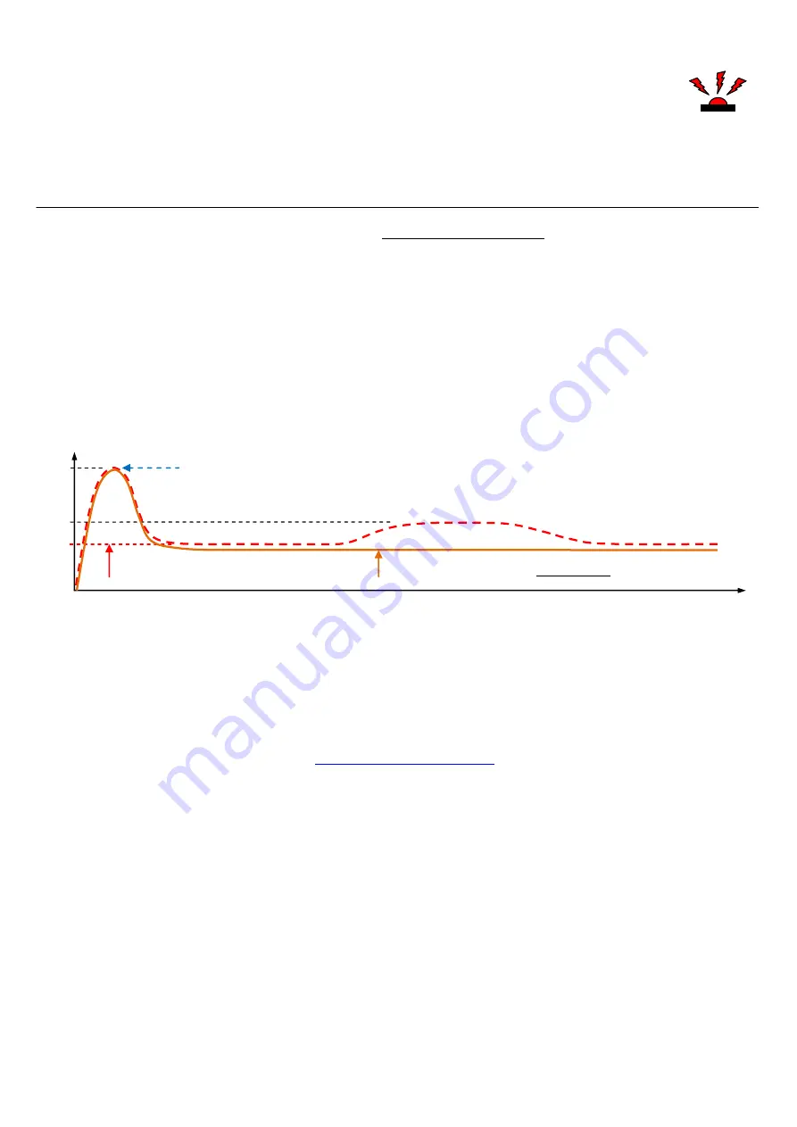
“. When voltage exceed this adjusted value, external braking resistor is activated (activates the
control signal for turned on of the braking resistors power electronic).
P19:
Maximal allowed current (limited)
(
calculated from the maximum short-time current of the controller
, the value in%)
This parameter set top value of average motor current (in all cases equal or smaller than nominal controller current). Parameter is defined as
% from max. short-time current.
Apply for both directions.
Acceleration current peaks are tolerated
. (
P19=100% is without reduction
).
P20:
Maximal power Backward
– additional motor PWM limiting to rotate in "backward“ direction
(% PWM)
Reducing engine power when turning back is an additional limitation of the maximum motor PWM to the set value.
The value is specified as a percentage PWM. (
P20=100% = without limitation of the motor PWM backward)
Overall, therefore, backward power limited both by restricting maximum current (P19), and motor PWM limitations, regardless of the current.
Applies the effect (the phenomenon), which occurs first.
Example:
for controller
25063
is nominal (=continuous, without time limits) current
250A,
short-time current is 350A
P19 = 70%, i.e. current will be reduced to
70% from 350A
, i.e.
to 245A
(value is valid for both direction of motor rotation)
P20 = 50%, i.e. power backward (resp. motor PWM backward) will be reduced to 50% of PWM, if previously does not apply current limita-
tion (P19)
P20 = 100 i.e. current backward will be not additionally reduced (i.e. in this example, for P19=70%, this is 245A).
P46:
Motor type + Automatic sensor settings
Sensorless
Sensors
Sensors – Automatic sensors settings (learning mode)
Possible is set sensorless as well as sensor motor (valid for SE version only).
Next possibility is „
Automatic sensors settings
– Learning mode
” include optimization of sensors position. We recommend make this setting first in
case of sensor motor. Partly you eliminate problems with no correct phase and sensors connection, partly you optimize sensors position
– this is, at
least, very recommend
ation, therefore sensor can be up to 20°out of optimize position inside some motors (and these not optimal position caused worse
efficiency).
Procedure of this setting is described in details in chapter
Automatic sensors settings procedure
P47:
Number of motor poles
This parameter is important for correct computing of mechanical output wheel rpm of the motor. When connect mechanical gear, necessary set
also gear ratio in parameter
P48
– necessary for example for helicopters. Without these values is not possible determine correct rpm. Also, if you
need to stabilize or reduce engine speed (rpm), parameters
P50
,
P86
, you must specify this parameter correctly
P51:
Motor PWM frequency
Automat
8 kHz
10 kHz
12 kHz
14 kHz
16 kHz
24 kHz
32 kHz
Using this parameter you set suitable frequency for motor control (PWM).
If you have a regular motor, set the lower frequency (8 - 12 kHz). If your motor requires higher frequency (ironless motors with extreme low
inductance), set the corresponding value (for example Tango by Kontronik need 32kHz, no recommend use lower value, etc.). Higher frequency
of motor control means higher switching losses of the controller and the controller is heated up more. This leads to higher cooling demands; even-
tually it is also necessary to proportionally reduce maximal power (current) of the controller.
Next occasion for higher frequency select (for example 24 kHz) can be audible whistling of some motors under runs.
Nominal
(max. continuous)
current
Starting current peak
Max. short time current
Up to 280% of nominal current
(depend on temperature, etc.)
100%
140%
280%
(250A)
(350A)
(700A)
Limited
average current
245A
( 70% from 350A )


