62 / 72
HBC-series V7 LV+MV
Maximal revolution of the output shaft Settings
For setting of Maximal revolution of unloaded motor (view from the motor, not mechanics of the system) necessary make following steps.
Set these parameters values by program
Controller 2
(obligatory data):
Parameter P50
–
max. requested rpm limit
(on the gear output),
RR
Parameter P47
– number of motor poles
PP
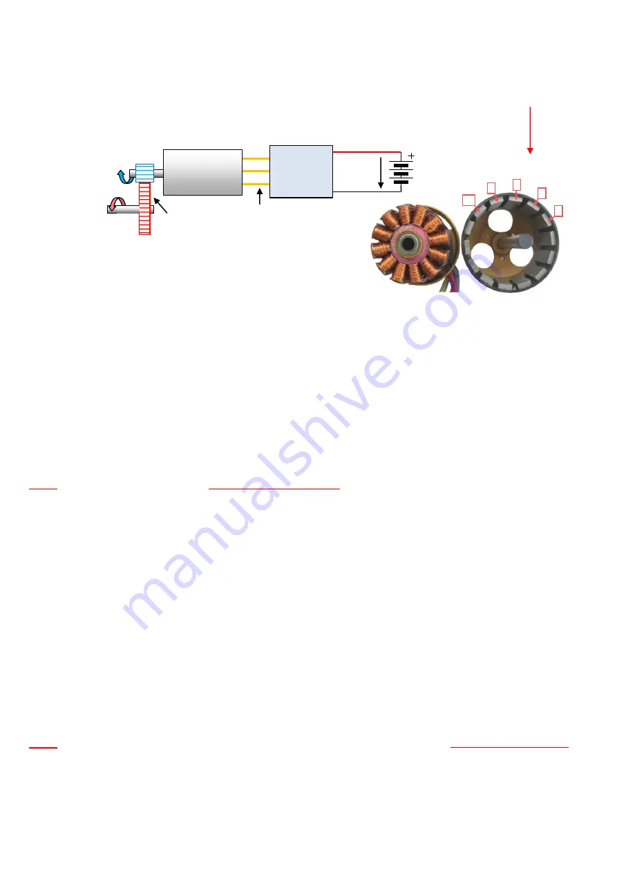
(determined every correct motor producer or you can count magnets, see picture)
Parameter P48
– gear ratio of gearbox
G
By these steps you have set maximal revolution. This settings is also revolution of 3
rd
throttle (flight mode
≡3) for HELI mode #2.
We recommend make checking, if controller range of rpm (electric) is sufficient as well as if motor choice is correct:
“Electric revolution
“ of the motor is the same as mechanical revolution only for 2-poles motor. Motors with higher number of poles have electric revolu-
tion (which must generate controller) proportionally higher (4 poles motor 2x, 6 poles motor 3x, etc.). Controller cannot work with higher revolu-
tion than specified in Technical data (for HBC controllers 250.000 rpm).
ER = RR
x
G
x
PP
/2
(electric revolution)
where:
RR
– requested mechanical revolution on the output shaft (for example helicopter’s rotor, etc.) [ rpm / V]
G
– gear ratio of gearbox
PP
– number of poles of the motor
Result must be <
250.000
rpm. In case of result is higher value, necessary lower gear ratio or use motor with lower number of poles.
Example:
requested mechanical revolution on the output shaft
RR
=
2.000
rpm.
gear ratio is 10 tooth of pinion, 50 tooth of main shaft, i.e.
G
= 50/10 =
5
number of poles of the motor
P
=
12
ER
=
RR x G x PP/2 = 2000 x 5 x 12/2
=
60.000 rpm
Result:
therefore this value 60.000 < 250.000,
controller is suitable for this system.
In next step necessary check motor, if requested output revolution is correct with available voltage.
Requested mechanical revolution of the
motor:
MR
= RR x G
where:
RR
– requested mechanical revolution on the output shaft (for example helicopter’s rotor) [ rpm / V]
G
– gear ratio of gearbox
We recommend this revolution no more than
70 - 80%
of
max. available mechanical revolution of the unloaded
motor (MRM).
In other case
not assurance that system has enough reserve of the power for reliable stabilization of the requested revolution.
Maximal available mechanical revolution of the unloaded
motor:
MRM
=
KV x U
where:
KV
– motor revolution [ rpm / V]
U
– supply voltage [V]
Example:
requested mechanical revolution on the output shaft
RR
=
2.000
rpm.
gear ratio is 10 tooth of pinion, 50 tooth of main shaft, i.e.
G
= 50/10 =
5
Motor
KV
=
800 rpm/V
Max. supply voltage:
(6 x Lipol), i.e. U
=
25,2 V
(charged battery) /
U
=
19,8 V
(discharged battery
– last 20% of energy available)
MR
= RR x G = 2.000 x 5 = 10.000 rpm
MRM
=
KV x U = 800 x 25,2 = 20.160 rpm
(charged battery)
MRM
=
KV x U = 800 x 19,8 = 15,840 rpm
(discharged battery)
Result:
Therefore requested (MM) 10.000 rpm is lower value than 70 - 80% of max. available revolution (=63%),
motor is suitable for this system.
Maximal revolution of the motor Settings
If it is important to limit the engine speed (not the transmission system), you need set only:
Parameter P86
–
max. requested rpm of the motor
MR
Parameter P47
– number of motor poles
PP
(see above)
For maximum engine speed of electrical ER are the same as stated above.
Gear Box
G
=
X:1
Output
shaft revolution
Motor
revolution
Motor
KV
– rpm / V
PP
– number
of poles
RR
MR
Controller
ER
Electric revolution
of the motor
MRM
U
Supply
voltage
(
Helicopter’s
rotor), etc..
Number of poles (magnets)
– for this example PP=14
1
2
3
4
14
Stator
Rotor


