33 / 72
HBC-series V7 LV+MV
Sensor motors and controllers
Sensor motors (BLDC motors with sensors) can have generally different connector and variously connected.
If you have a motor with any sensor connector or if you are not 100% sure of connecting the motor sensor wires and/or motor power
cables on separate phases,
it is necessary make to
first "Automatic sensor settings"
. This mean before any start or testing - the first
engine start with the sensors must be in "Automatic sensor settings" mode !
Otherwise, you risk the destruction of or damage to the controller.
This is very advantageous to make, even if you know the good connection of phases and sensors, because many of these engines does not
have sensors in its optimal position in relation to the stator and during operation created unnecessary losses - "Automatic sensor settings" elim-
inates this imperfections and optimize sensor settings for such engines.
If you replace the engine, repeat this initially settings.
IMPORTANT: If the motor spins in reverse than you need, necessary change the direction of rotation in parameters. You can also swap
the other two phases as for sensorless motor, but must run again "Automatic sensor settings", the learning process.
In all cases it is necessary to strictly correspond Pin connector description,
see "
Summary of possible inputs / outputs
If you are not sure the sign and the connecting of each sensors (Sensor A, Sensor B, Sensor C) or as the phases marking (A, B, C),
does not matter, with this controller in the "
Automatic sensor settings
" to order.
Other wires must not be mistaken !
Note:
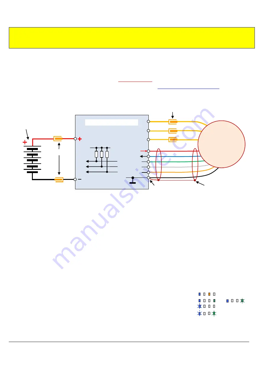
Shielded cable to the engine sensors, when used with shielded cable, must be connected to ground (GND) only for the controller side
- must not be used as a negative lead for sensors!
Shielding must not be connected to ground (GND, chassis) anywhere else than on the sensor connector of controller !!!
Pull up resistors for the individual sensors are integrated in the controller. They may (but need not) also be on the side of the engine
(2K2 resistor)
. In any case, the feeding of sensors (on the engine side) must be filtered by 100nF ceramic capacitors or a better by 1
F.
The temperature sensor may not be connected to external pull-up resistors
.
Automatic sensor setting procedure
This setting is necessary make on the not loaded motor
– i.e. without propeller or pinion for gear.
In this procedure,
you may not also
have limited speed or current.
The procedure can also be made at reduced power supply voltage than the nominal operating voltage (of course in the range of operating volt-
age) - some unloaded motors could in that case operating at full voltage exceed its own speed limit!
1)
connect motor to controller, include sensor cable, connect to PC and turn on controller.
2)
in program „
Controller 2
“ set parameter P46,
Motor type
to „
Sensor motor
– Automatic sensor setting
“
3)
write this setting to controller by button
„
Write setting
“
4)
turn off controller (USBCOM 4 is possible disconnect)
5)
turn on transmitter
6)
when controller is not connected to receiver or signal source, connect now, to throttle channel (for OPTO version also turn on receiver
supply / gen5V supply for optocoupler in the controller)
7)
turn on controller again,
if you don´t set throttle limits (= you have automatic limits), must go through the initial setup limits procedure
, i.e.
until state of lighting
blue LED
and
yellow LED
(throttle in Neutral position)
……..…………………….....
8)
move throttle stick to full throttle forward, controller start run motor and automatically stop …….............. or
9)
LED indicate correct finishing of this operation by
blinking of
blue LED
…………………………………..
( in case of some problem start
blinking
all
LEDs
…………………………………………………………… )
10)
if you don´t see LEDs (controller is somewhere inside model) you can check correct finishing of this procedure by this way:
move throttle stick back to STOP position and try increase throttle again
motor must not start run now
11) switch-off controller, sensors position and phase are correct and optimize, after correct finishing procedure controller automatically switch
Motor type
parameter to “
sensors
” – you can check this also by read data via program
Controller 2.
12) when you turn on controller now, working with sensors
– you can connect load to motor (propeller, pinion, ..
Note:
After correct finished procedure controller
automatically switched parameter settings to “sensor motor“, you can check this via reading
data from the controller by program „
Controller 2
“. This setting is remembered (up to next start of this procedure).
When procedure finishes not correctly, checks connectors, sensor connections, and start procedure again.
Cable shielding connection
to GND only here !
Power
connectors
Traction
battery
(supply)
Controller HBC- series
(GND)
BAT.
A
B
C
Power
connectors
or direct motor connection to the
controller (without power connectors)
GND
Sensor C
Sensor B
Sensor A
Motor temperature
Sensors
f5V
Cable shielding
BLDC motor
with sensors


