18 / 72
HBC-series V7 LV+MV
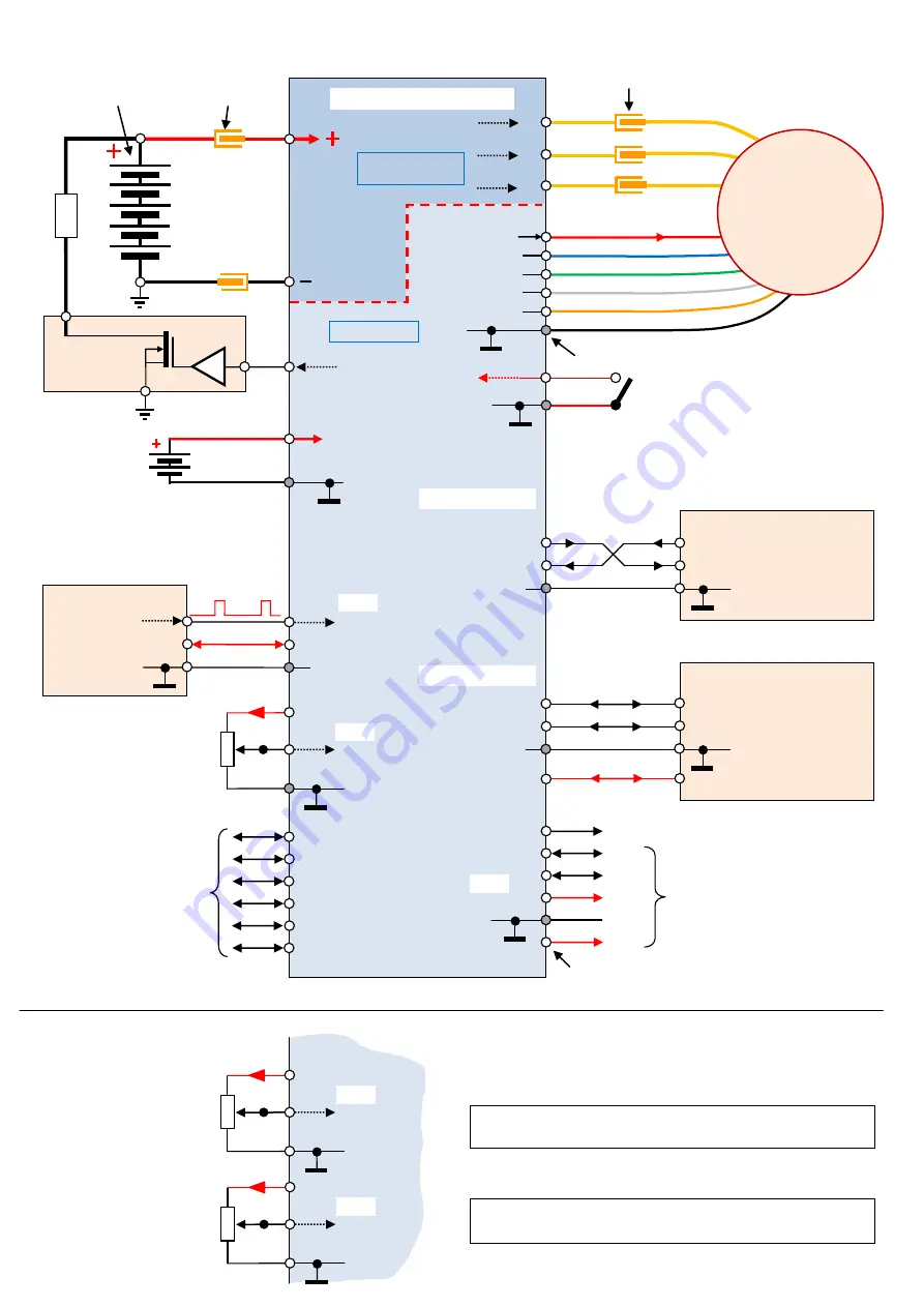
Basic controller connection
Note 1:
Both inputs
INP_1
and
INP_2
can be the same, both should be controlled by voltage or potentiometer, both can be
controlledby input PWM, etc.
Switching
element
FET driver
Power
connectors
Traction battery
(supply)
Power
connectors
or direct motor connection to the
controller (without power connectors)
GND
Sensor C
Sensor B
Sensor A
Connector for motor sensors
INP_1
GND
1 kΩ
GND
+3.3V
(GND)
Signal
source
-----------
Control
system
Potentiometer
or control voltage
control voltage
Input control PWM
(+5V)
GND
INP_2
Braking resistors
driving
B
ra
k
ing
r
e
s
is
to
rs
Auxiliary control
logic signals
Auxiliary output
signals
ICS-2
connector
GND
GND
(+5V)
(+5V)
+3.3V
SCL
SDA
BL_1 (Driving of the braking lights, indication, etc.)
ICS-2
I2C link,
communication with external modules,
communication with PC (USBCOM 4),
parameters settings, update firmware,..
feeding of ext. modules
Note 2
: Not every type of controller has all the inputs,
outputs, and options
Note 3
: Some inputs, outputs can be galvanic isolated
(as input PWM, CAN, RS-485, etc.)
GND
1 kΩ
GND
+3.3V
Potentiometer
or control voltage
control
voltage
INP_2
GND
1 kΩ
GND
+3.3V
Potentiometer
or control voltage
control
voltage
INP_1
Auxiliary battery
for feeding electronics
Control system
display
, BMS, …
Data (controlling)
communication
(GND)
(+5V)
RS 485
CAN
GND
RS 485
CAN
Communication _2
Control system
display
, ….
Data (controlling)
communication
(GND)
RS 232 TTL
GND
RS 232 TTL
Communication _1
TxD
RxD
TxD
RxD
Motor temperature
Sensors feeding
+14V
35V
Electronics feeding
GND
GND
switch
V1
BATT
(GND)
A
B
C
Controller HBC- series
Power board
- motor driving
Control board
*)
*)
controllers up to 63V (
LV
types) can be used traction voltage to feeding of the electronics - must be specified in the order
BLDC motor
with or without
sensors
+5V or +10V


