background image

T

Table Top Removal . . . . . . . . . . . . .  2 - 8, 2 - 11
Thread Saddle . . . . . . . . . . . . . . . . . . . . . .  3 - 1

Removal . . . . . . . . . . . . . . . . . . . . . . . .  3 - 1

Thread Tensioner Assembly

Replacement . . . . . . . . . . . . . . . . . . . .  3 - 9

Troubleshooting LEDs and Test Points . . . .  1 - 6

V

Voltage Adjustments . . . . . . . . . . . . . . . . .  2 - 8

W

Warranty Considerations . . . . . . . . . . . . . .  1 - 3
Wide Angle Cap Frame . . . . . . . . . . . . . . .  4 - 1

Cap Frame . . . . . . . . . . . . . . . . . . . . . .  4 - 4
Cap Support Pads. . . . . . . . . . . . . . . . .  4 - 2
Cap Supports . . . . . . . . . . . . . . . . . . . .  4 - 1
Clip Posts . . . . . . . . . . . . . . . . . . . . . . .  4 - 3
Driver Bar Cable . . . . . . . . . . . . . . . . . .  4 - 2
Spindles On The Clamps. . . . . . . . . . . .  4 - 3

X

X Beam Assembly . . . . . . . . . . . . . . . . . . .  2 - 17
X Drive Belt. . . . . . . . . . . . . . . . . . . . . . . .  2 - 19

Replacement . . . . . . . . . . . . . . . . . . .  2 - 19
Belt Tension . . . . . . . . . . . . . . . . . . . .  2 - 20

X Motor Replacement . . . . . . . . . . . . . . .  2 - 17
XYZ Motor Driver Amplifiers. . . . . . . . . . .  2 - 15

Y

Y Drive Belt. . . . . . . . . . . . . . . . . . . . . . . .  2 - 25

Replacement . . . . . . . . . . . . . . . . . . .  2 - 25
Tension Adjustment . . . . . . . . . . . . . .  2 - 28

Y Motor

Belt Tension . . . . . . . . . . . . . . . . . . . .  2 - 23
Replacement . . . . . . . . . . . . . . . . . . .  2 - 21

Z

Z Motor

Belt Tension . . . . . . . . . . . . . . . . . . . . .  3 - 3
Replacement . . . . . . . . . . . . . . . . . . . .  3 - 2

Z Shaft Encoder . . . . . . . . . . . . . . . . . . . . .  3 - 4

Introduction . . . . . . . . . . . . . . . . . . . . .  3 - 4
Inspection. . . . . . . . . . . . . . . . . . . . . . .  3 - 5
Installation . . . . . . . . . . . . . . . . . . . . . .  3 - 6
Calibration . . . . . . . . . . . . . . . . . . . . . .  3 - 7

INDEX

110344-01, Revision B

ii

EMT 1 Technical Manual

Summary of Contents for EMT 1

Page 1: ... Single Head One Needle Tubular Goods Hooping Technical Manual for the EMT 1 embroidery peripheral Part Number 110344 01 Revision B ...

Page 2: ...thout prior written approval of Melco Embroidery Systems Melco reserves the right to revise this publication and to make changes in it at any time without obligation of Melco to notify any person or organization of such revisions or changes All precautions have been taken to avoid errors or misrepresentations of facts equipment or products However Melco Embroidery Systems does not assume any liabi...

Page 3: ...8 2 Service Maintenance except embroidery head General 2 1 Drive Belt Tensions 2 1 Keyboard Section 2 2 Keyboard Display Replacement 2 2 Display Screen Intensity 2 3 Disk Drive 2 4 Lamp Assembly 2 4 Bobbin Winder 2 5 E Stop Switch Replacement 2 6 Power Distribution Section 2 8 Voltage Adjustments 2 8 Remove Table Top 2 8 Module Replacement 2 8 Electronics Section 2 11 Remove Table Top 2 11 Remove ...

Page 4: ...oduction 3 4 Inspection 3 5 Installation 3 6 Calibration 3 7 Needle Case 3 9 Thread Tensioner Assembly Replacement 3 9 Thread Check Spring Replacement 3 10 Thread Check Spring Adjustment 3 11 Adjustment Hints 3 11 Replacing The Needle Bar Presser Foot Associated Parts 3 12 Needle Case Removal 3 14 Jump Stitch Solenoid Replacement 3 16 Jump Stitch Solenoid Adjustment 3 17 Plunger Positioning 3 17 B...

Page 5: ...justments Wide Angle Cap Frame 4 1 Cap Supports 4 1 Cap Support Pads 4 2 Driver Bar Cable 4 2 Spindles On The Clamps 4 3 Clip Posts 4 3 Cap Frame 4 4 Table of Contents EMT 1 Technical Manual iii 110344 01 Revision B ...

Page 6: ...This page intentionally left blank Table of Contents 110344 01 Revision B iv EMT 1 Technical Manual ...

Page 7: ...al and various service requirements 2 service maintenance of all the machine areas except the embroidery head 3 embroidery head maintenance and 4 accessory adjustments Sections 2 3 and 4 address mechanical disassembly and replacement of the major components of the embroidery peripheral and any related machine adjustments Standard Conventions Used In Manual Throughout this manual abbreviations and ...

Page 8: ...s for communicating the information It may be used to clarify certain portions of text or to call attention to other items previously mentioned or mentioned later in the procedure Glossary Of Terms Several words or terms are used in this manual that are unique or specialized in use with the embroidery industry or Melco embroidery equipment A glossary of these terms is located in the operation manu...

Page 9: ...Embroidery Peripheral is sensitive to static electricity Any time work is performed inside covered areas of the embroidery peripheral the person performing the work MUST be using a static grounding strap WARNING Failure to use a grounding strap or failure to practice other good maintenance repair techniques may cause damage to the machine and possible harm to personnel Grounding Strap Use The grou...

Page 10: ...failures may result Functional Arrangement The EMT 1 is functionally arranged into several sections including the electronics a power supply section the keyboard and disk drive the Embroidery Head and the Carriage section Figure 1 1 shows the general locations of these and other functional parts of the embroidery peripheral Keyboard and Disk Drive thread saddle electronics section under rear table...

Page 11: ...lso be used in other embroidery peripherals produced at Melco Therefore you must tell the CPU board what peripheral it is being used in If the CPU PCB is ever replaced you must reconfigure the peripheral before using it again CAUTION If the EMT 1 is not configured with the correct Peripheral Program it will not run properly and may become damaged The second configuration item is the Network Addres...

Page 12: ...ccur To access this area remove the screws holding the cover flip the cover over so the lettering on the cover is visible as shown in Figure 1 2 and reinstall the cover in the same holes but above the LED opening The lettering on flip side of the cover is a brief title for each of the LED and test point locations You may also refer to Figure 1 3 for this information lettering on metal cover indica...

Page 13: ...ithout load 30 to 37 VDC 36 VDC with 20 100 load 34 2 to 37 8 VDC 24 VDC 22 8 to 25 2 VDC 12 VDC 10 8 to 13 2 VDC 12 VDC 11 4 to 12 6 VDC 5 VDC 4 9 to 5 1 VDC Note 36 VDC When the peripheral is first turned on and before the program is downloaded the 36 0 VDC LED may be blinking This is normal But after the machine initializes and the motors become energized if the blinking does not stop the power...

Page 14: ...or Belt Tension 7 1 pounds X Carriage Friction 5 2 pounds Y Beam Friction 12 4 pounds NOTE A special force gauge has been designed for adjusting the belt tensions using unique methods that are representative of these tension specifications X Home Sensor Position centered within 0 015 inches Y Home Sensor Position 7 09 0 015 inches from arm mounting holes in the carriage relative to the needle plat...

Page 15: ...on of good maintenance and repair techniques including concerns with static electricity WARNING Failure to practice good maintenance and repair technique may result in injury to personnel performing the work and damage to the equipment NOTE The Warranty is exclusive of and may be VOID if poor maintenance practices have caused damage to the equipment Drive Belt Tensions CAUTION Damage to the machin...

Page 16: ...isplay assembly 3 Remove the cable strain relief plate from behind the keyboard display assembly 4 Remove the 4 screws from the base plate of the assembly to loosen the keyboard display assembly and cover 5 Carefully slide the assembly forward until you can access the cables 6 Pinch the locking lever of the small 2 wire connector and remove it from the keyboard PCB 7 Use a 3 16 nut driver and remo...

Page 17: ... by reversing the preceding steps NOTE When re attaching the PCB to the cover be certain the ground wire is attached at the 4th screw and that when the screws are tightened the buttons do not stick in the cover holes when pressed Display Screen Intensity During the adjustment of the display intensity the EMT 1 must be turned on so the result of the adjustment may be observed 1 Locate the intensity...

Page 18: ...data ribbon orient the harness so the edge with the colored stripe indication pin 1 is lying adjacent to the power harness Lamp Assembly The halogen bulb replacement is described in the operation manual The bulb has 2 pins that simply plug into the base socket at the end of the lamp post The bulb case must be removed by rotating it counter clockwise off the base to access the lamp disk drive side ...

Page 19: ...ator lever away from the start position by hand The bobbin winder motor is equipped with a thermal switch to protect the motor and circuitry in the event of an overload condition If the bobbin winder stops due to an overload or overheating 1 Move the actuator lever to the OFF position 2 Clear the obstruction and or lubricate the drive shaft 3 When the motor cools the thermal switch will reset 4 Mo...

Page 20: ...t the inside surface of the cover see Figure 2 7 4 Refer to Figure 2 7 to locate the small square opening in the switch block through which you will see the small locking tab on the switch assembly body 5 Remove the switch block by depressing the tab on the assembly body through the opening in the switch block and sliding the switch block off the end of the assembly body left side tensioner cover ...

Page 21: ... When the new switch block is pressed onto the end of the switch assembly transfer the wires one at a time to keep them in the proper order refer to the diagram in Figure 2 8 As shown in the figure the two wires labeled with C and C are connected to the pole marked C The two wires labeled with D and D are connected to the pole marked D wire C switch block wire D wire D wire C switch pole markings ...

Page 22: ...inder is installed you must disconnect the two harnesses going to the bobbin winder assembly as you lift the table top upward 2 Lift the table top up and disconnect the bobbin winder harnesses if the bobbin winder assembly is installed Remove the table top to a safe storage area Module Replacement The power distribution module is replaced as an entire assembly regardless of which of the areas incl...

Page 23: ...ove the power distribution module from those two screws you must first slide it slightly forward and then to the right Carefully lift the module out of the peripheral 9 Put the new power distribution module into place and push the open ends of the slots at the left of the module under the loosened screws near the peripheral wall power switch harness four screws at the rear of the peripheral the tw...

Page 24: ... 12 Reinstall the three harnesses in the top the power switch harness at the side and the ground wire to the stud near the rear left corner of the power distribution section NOTE When a new power distribution module is installed there is no requirement for adjusting any voltages 13 Reinstall the left rear table top with optional bobbin winder assembly 14 Reattach the power cord to the peripheral v...

Page 25: ...able top upward 2 Lift the table top up and disconnect the lamp assembly harness Remove the table top to a safe storage area Remove Card Cage Cover 1 Turn OFF the power switch to the EMT 1 and remove the power cord from the power source electrical outlet and the rear of the machine 2 To remove the card cage cover remove the 10 screws and associated hardware from around the cover as shown in Figure...

Page 26: ... PCB is the first PCB located to the front of the card cage as shown in Figure 2 11 Refer to the following procedure for replacing the CPU PCB 1 Turn OFF the power switch to the EMT 1 2 Remove the card cage cover and install a static grounding strap between the working surface and the personnel performing this procedure 3 Grasp the CPU at the top corners and gently rock it out of its connectors in...

Page 27: ...cage cover and install a static grounding strap between the working surface and the personnel performing this procedure 3 Disconnect the Ethernet cable from the end of the PCB at the Ethernet card edge mounting bracket 4 Remove the screw and washer at the card edge mounting bracket for the PCB Low Voltage Driver PCB Interface PCB CPU PCB Ethernet network PCB XYZ Motor Driver Amplifier PCB Backplan...

Page 28: ...el performing this procedure 3 Grasp the Interface PCB at the top corners and gently rock it out of its connectors in the backplane PCB Remove the Interface PCB 4 Replace the Interface PCB by reversing the previous steps 5 Remove the static grounding strap and replace the card cage cover 6 Reinstall the right rear table top Low Voltage Driver PCB The Low Voltage Driver PCB is positioned inside the...

Page 29: ... and gently rock it out of its connectors in the backplane board Remove the XYZ Motor Driver Amplifiers PCB 6 Replace the PCB by reversing the previous steps 7 Install the screw and washer at the card edge mounting bracket to secure the printed circuit board 8 Reconnect the 2 cables to the end of the XYZ Motor Driver Amplifiers PCB and tighten the screws in the cable connectors 9 Remove the static...

Page 30: ...e the cover over the backplane PCB connectors Use the same hardware that previously secured it 11 Reinstall the card cage to the base of the electronics section securing it with the four screws removed earlier 12 Reconnect the cables to the backplane PCB and reinstall the screws holding the cover over the backplane PCB connectors 13 Reinstall all the upright printed circuit boards as earlier descr...

Page 31: ...e to replace the X motor and adjust the X drive belt tension Motor Replacement NOTE This procedure requires a specific Melco force gauge p n 995585 01 for proper belt adjustment after replacing the motor 1 Turn OFF the power switch to the EMT 1 and remove the power cord from the power source electrical outlet and the rear of the machine drive belt tensioning screw X beam tensioner block mounting s...

Page 32: ... flange to the new motor shaft Apply a small amount of Loctite 222 hardware adhesive or equivalent and reinstall and tighten the screw 10 Orient the new motor with the encoder wires facing down and outward and the motor drive wires facing directly toward the X harness interface PCB 11 Referring to the orientation described in the previous step install the new motor into the beam using the existing...

Page 33: ...to Figure 2 14 and loosen the drive belt tensioning screw then the two tensioner block mounting screws to loosen the drive belt 4 The existing X drive belt is clamped and held to the X carriage plate by two flat head socket screws a clamp and a spacer The screws go through holes in the belt as well Remove the two flat head socket screws and associated clamp and spacer to free the belt at this area...

Page 34: ... screws to snug the belt tensioner block to the X beam frame 4 Move the X carriage all the way to the left of the beam until it mechanically stops 5 Orient the Melco force gauge p n 995585 01 vertically with the push end down Place the finger of the push end against the top of the lower loop of the belt and mid way between the two pulleys at the belt ends see Figure 2 16 An X home cable clamps is ...

Page 35: ...ith a ripple in it to reach the X carriage surface but with some yielding of position To form this ripple simply form the middle section of the piece of Velcro around a 2mm or equivalent hex wrench as you attach it to the tensioner block When the Velcro is securely attached twist the wrench out from between it and the block A rippled portion of the Velcro piece remains Y Motor The Y axis drive mot...

Page 36: ...or shaft then loosen the set screw in the Y motor pulley and remove the pulley 9 Remove the four socket head cap screws that secure the motor to the motor bracket and gently let the motor lie on the peripheral base 10 Remove the belt tensioning socket head cap screw and remove the motor bracket 11 Slide the motor out of the Y shaft bearing support bracket far enough to note the orientation of the ...

Page 37: ...aring support bracket with the two socket head cap screws Leave the screws slightly loose 17 Reattach the in line connector for the motor power harness 18 Replace the belt onto the motor and Y shaft pulleys and reinstall the belt tensioning socket head cap screw through the hole in the motor bracket tensioning tab into the threaded hole in the tensioning tab of the Y shaft bearing support bracket ...

Page 38: ...ly The other end of the force gauge plunger will be resting against the top edge of front wall of the power distribution section 5 Place a pencil mark on the plunger at the location where the inside surface of the power distribution section wall touches the plunger 6 Measure 0 2 inch toward the end of the plunger from the mark made in the previous step and place another pencil mark on the plunger ...

Page 39: ...ion on the Y motor belt If the belt tension is too tight rotate the belt tensioning screw slightly counter clockwise to allow the motor bracket to move upward to reduce the belt tension 12 After moving the motor bracket in the previous step retighten the two motor bracket securing socket head cap screws and check the tension again 13 Repeat this procedure until the proper tension is attained Y Dri...

Page 40: ...he left side of the peripheral remove the Y home flag to gain access to the belt clamp 9 Push the now slack belt aside far enough to get a hex wrench through the access holes in the base of the Y carriage mounting bracket and into the socket head cap screws securing the Y drive belt to the under side of the Y carriage block Remove the screws and belt mounting clamp 10 Slide the old belt out from a...

Page 41: ... slack in the belt and provide some amount of tension 14 If the Y drive belt on the left side of the peripheral was replaced reinstall the Y home flag that was removed earlier to gain access to the belt clamp 15 Refer to the Y drive belt tension adjustment procedure Y carriage block belt mounting clamp and screws cap head screws for adjusting belt tension access holes Y drive belt Figure 2 20 Y Dr...

Page 42: ... check the Y drive belt tension with the Melco force gauge p n 995585 01 by the following steps 5 Place the finger of the pull end of the force gauge through the beam support slot in the table top above the Y drive belt Position the gauge mid way between the front pulley and the Y carriage block 6 Press the force gauge plunger down until the finger is between the two loops of the Y drive belt then...

Page 43: ...ase tension on the Y drive belt or loosening the screws to reduce the tension 10 Check the Y drive belt tension on the other side of the peripheral using the same method as in the previous steps The tensions of the two belts should be within 0 25 pounds of each other 11 If needed adjust the other Y drive belt to the proper tension according to the above specifications 12 Repeat this procedure unti...

Page 44: ...This page intentionally left blank 2 30 X Beam Assembly EMT 1 Technical Manual Melco Embroidery Systems ...

Page 45: ...m and Bed Assembly The arm and bed assembly provides a stable embroidery head platform All other components of the embroidery head are attached to this assembly Inside the arm and bed assembly are the shafts belts and pulleys that drive the needle and rotary hook Attached to the outside of the arm and bed assembly are the Z drive motor needles case and thread saddle Thread Saddle Removal The threa...

Page 46: ... Z motor harness at the in line connection going into the cable to the electronics card cage connectors 4 Using a properly sized open end wrench loosen the two motor bracket mounting tensioning nuts See Figure 3 3 to take the tension off the belt Thread Saddle front mounting screws Thread Saddle rear mounting screws Figure 3 1 front mountings for Thread Saddle rear mountings for Thread Saddle Figu...

Page 47: ...ng bracket to slide down as the drive belt catches the assembly in the center of the drive pulley 12 Make certain the bottom loop of the drive belt is centered in the drive pulley If not loosen the drive pulley set screw and adjust the pulley so it is directly below the main Z drive pulley 13 Tighten both Z drive pulley set screws Belt Tension Note This procedure requires a Gates 5M Tensiometer Me...

Page 48: ...e Z motor allows a larger window of error The purpose of this window is to keep the motors from oscillating around the null hunting for absolute position The green LED marked ZINDEX on the front of the peripheral see Figure 3 4 can be used to see if the CPU is in fact receiving a head up or mark pulse from the encoder This indicates that the encoder and associated cables are functional It should b...

Page 49: ... top of the CPU Most likely this LED will not be glowing It is only supposed to glow for a 1 degree duration each revolution of the Z shaft encoder 5 Rotate the embroidery head manually in a clockwise direction when viewing from the rear of the machine This rotation can be performed by rotating the shaft pulley that is driven by the motor belt see Figure 3 5 6 While slowly rotating the head check ...

Page 50: ...ps 1 Turn the machine OFF then disconnect the power cord from the power source 2 Remove the cover from the rear of the embroidery head 3 Disconnect the encoder cable from the current shaft encoder see Figure 3 5 4 Loosen the two coupler cap head screws A that secure the coupling to the Z encoder shaft see Figure 3 5 5 Loosen and unthread the jam nut on the encoder shaft Shaft Pulley Z Encoder Z Mo...

Page 51: ... following procedure Calibration CAUTION Failure to properly calibrate the Z shaft encoder after replacing it may cause damage when attempting to operate the machine Note This procedure leads to a calibration which requires the use of a special service tool the Melco head up alignment pin tool 995338 01 or the Melco 10 needle head up fixture p n 995673 01 1 Install the Z shaft encoder as described...

Page 52: ...ad screw on the encoder coupling to Z shaft 10 Remove the screw and apply a small amount of Loctite 222 hardware adhesive or equivalent and reinstall and tighten it 11 Return to the first encoder coupler cap head screw remove the screw and apply a small amount of Loctite 222 hardware adhesive or equivalent then reinstall and tighten it 12 Turn the embroidery peripheral OFF and attach the network c...

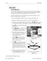
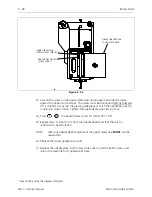
Page 53: ...insert the thread tensioner into the hole in the needle case casting 6 Reattach the in line thread break wire and pin into the rear of the thread tensioner post 7 Snug the set screw to secure the thread tensioner in place After performing the check spring adjustment on Page 3 11 you must tighten the set screw securely 8 After installation the tensioner disk may wobble while it is rotating This is ...

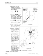
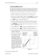
Page 54: ...sert the straight length of spring wire that is inside the check spring coil into the groove cut in the tensioner post as shown 5 Position the tensioner post mount so the check spring protruding through the slot is near but not touching the top end of the slot During the adjustment of the check spring the spring being restricted by the thread break contact post must be able to move counterclockwis...

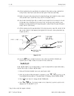
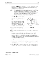
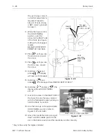
Page 55: ...A certain amount of stroke distance is required to take up the thread slack and cinch the stitch properly If the check spring is too tight against the thread break post it will not retract far enough to make that stroke needed for a good tight stitch False thread break messages may also occur with excessive rotation If you rotate less than 60 degrees you will begin to lose the force needed to make...

Page 56: ...of the needle case so the needle bar can be removed out the top of the needle case 6 Loosen the needle clamp set screw and remove the needle and needle clamp from the bottom of the needle bar 7 Next loosen the needle bar stop clamp black clamp CAUTION After the next step the needle bar is free to be moved out the top of the needle case Use care so the springs and other parts do not fly out of posi...

Page 57: ...13 Reinstall the covers and plug that were removed during this procedure The needle bar height must now need to be properly adjusted Refer to the hook timing procedure later in this chapter for information in making this adjustment Needle Bar Holding Spring 1 Washer Under Spring 2 Rubber Bumper 5 Presser Foot top through hole 9 Nylon Piece 11 Lower Casting Piece 13 Presser Foot lower through hole ...

Page 58: ...ie down holding the thread break and ground wires to the top of the head 5 Disconnect the thread break and ground wire in line connector located just behind where the tie down was removed see Figure 3 13 6 Remove the 3 screws and e stop jump stitch solenoid cover from the needle case see Figure 3 14 Place the e stop assembly on the top of the head E Stop and Jump Stitch Solenoid wires TOP VIEW Fro...

Page 59: ...dle case to the front of the embroidery head see Figure 3 15 Allow the needle case to come off in your hand when the screws are removed 9 To reinstall the needle case reverse the order of the previous steps Four Needle Case screws remove in step 7 Needle Case Cover remove in step 6 Needle Case Cover Plate remove in step 6 Figure 3 15 Needle Case Removal 3 15 110344 01 Rev B 3 Embroidery Head Maint...

Page 60: ...e tie down was removed see Figure 3 16 5 Disconnect the jump stitch harness wires from the in line connector and connect the wires from the new jump stitch solenoid where the old ones were removed 6 Refer to Figure 3 17 and remove the top and bottom screws ONLY of the jump stitch solenoid bracket and then remove the solenoid and the solenoid bracket as one piece Thread Break Ground Wire Harness Co...

Page 61: ... to the following adjustment procedure for the proper adjustments Jump Stitch Solenoid Adjustment If a jump stitch solenoid has been replaced perform the following adjustments NOTE The needle case must be removed to make this adjustment Plunger Positioning Plunger Position 1 The jump stitch solenoid must be positioned so the plunger is close enough to actuate the needle bar driver reciprocator whe...

Page 62: ...he solenoid and bracket assembly Bracket Position 1 The solenoid and bracket assembly should be far enough forward so the plunger will cause the reciprocator to rotate enough to release the needle bar during the jump stitch cycle Bracket Position 2 The solenoid and bracket assembly must not be so far forward that it causes the reciprocator to rotate to its mechanical rotational limit This may caus...

Page 63: ...itch solenoid and test embroider a large letter 6 inch block I for example to check the machine for proper jump stitch operation After attaching the new solenoid and bracket assembly to the embroidery head and check the alignment Be sure the plunger contacts the reciprocator mechanism and the reciprocator mechanism does not contact other internal head parts when the solenoid is energized The two w...

Page 64: ...m the connecting rod by pulling it straight out of the head Discard the reciprocator 6 On the new reciprocator place a drop of machine oil on the reciprocator connecting stud located on the lower back side of the reciprocator 7 Install the new reciprocator into the head Be certain it is oriented properly and insert the connecting stud onto the connecting rod 8 Add two drops of machine oil onto the...

Page 65: ... until the flat near the top faces the left side of the head 12 Pull the needle bar guide shaft down until it seats into the lower hole be certain the retaining clip is located low enough so the reciprocator will not hit it during its down stroke and the roller bearing is loose enough to rotate freely 13 Tighten the set screw on the left side of the head to secure the needle bar guide shaft Reinst...

Page 66: ...ss keys The head rotates to the Head Up position and the LCD displays GO TO HEADUP 110 0 6 Locate the screw that is visible on the right side of the hook assembly as shown in Figure 3 20 Loosen this screw one or two turns 7 Press the key 6 times until the second hook screw is visible also as shown in Figure 3 20 Loosen this screw one or two turns 8 Press 6 more times and another screw will become ...

Page 67: ... above the rotary hook grasp the needle bar clamp and pull down until the needle goes into the slot in the bobbin basket and the needle bar catches securely 17 Refer to Figure 3 22 for aligning the hook point to the needle At the same time refer to Figure 3 23 and position the hook point so the gap between the needle scarf and the hook point is 0 002 to 0 020 about the width of a thread May not be...

Page 68: ...ecure the retaining fingers position 22 Use the key to rotate the hook to the other two HOOK SCREWS and tighten each of these screws to secure the hook assembly Needle Depth If the needle depth is out of adjustment it must be adjusted for proper embroidery Follow these steps to adjust needle depth 1 Remove the lower needle case cover see Figure 3 26 2 With the machine ON and ready for operation pr...

Page 69: ...ble in the hook assembly If the needle s eye is in the acceptable range skip the next few steps and go to Step 16 If the needle s eye is not in the acceptable range continue this procedure with the next step 8 Loosen the needle bar clamp screw silver clamp shown in Figure 3 26 9 Slide the needle bar up or down until not more than 1 8 of the needle s eye should be visible in the hook assembly If yo...

Page 70: ...Repeat steps 5 6 and 7 to check the needle depth and that there is no restriction to head rotation NOTE After any needle depth adjustment the upper dead stop MUST also be readjusted 16 Replace the lower needle case cover 17 Replace the needle plate both rotary hook covers and the bobbin case and return the machine to its operational state May not be exactly the degrees indicated upper dead stop cl...

Page 71: ...CD displays GO TO HEADUP 110 0 7 Hold down and press the display will read NEEDLE DEPTH 180 0 8 Hold down and press the display will read HOOK TIMING 201 0 9 Grasp the needle bar clamp and pull down until the needle goes into the slot in the bobbin basket and the needle bar catches securely 10 Check to see if hook timing is correct before you proceed You must check the hook point s alignment with ...

Page 72: ...l read NEEDLE DEPTH 180 0 16 Hold down and press the display will read HOOK TIMING 201 0 17 Loosen the screw on the RIGHT SIDE of the hook the one that was colored with the felt tipped marker while you hold the Hook in position 18 Line the hook up in the approximate HOOK TIMING position refer to Figures 3 27 and 3 28 19 Grasp the needle bar clamp and pull down until the needle goes into the slot i...

Page 73: ...tting is correct as shown in Figures 3 27 and 3 28 22 Press the key to rotate the the hook to access the other two hook screws and tighten them securely 23 After checking and setting hook timing as required replace the needle plate rotary hook covers and the bobbin case then return the machine to its operational state Hook Timing Adjustments Only 3 29 110344 01 Rev B 3 Embroidery Head Maintenance ...

Page 74: ...This page intentionally left blank 3 30 Rotary Hook EMT 1 Technical Manual Melco Embroidery Systems ...

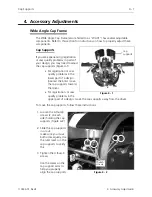
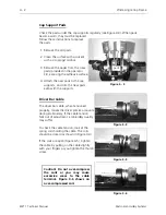
Page 75: ...t the brim move the cap supports toward the driver For registration or sew quality problems in the upper part of a design move the cap supports away from the driver To move the cap supports follow these instructions 1 Loosen the 4 thumb screws 2 on each side holding the cap supports Figure 4 2 2 Slide the cap supports in or out make sure you move both sides equally Use the ruler marks on the cap s...

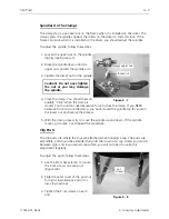
Page 76: ...ar cable when tensioned properly moves the driver precise amounts during embroidery If the cable tension falls out of adjustment embroidery quality may suffer To check the cable tension look at the spring coils holding the cable The coils should be closed as shown in Figure 4 4 If the coils are open Figure 4 5 tighten the cable by pulling on the cable slightly with your fingers as you tighten the ...

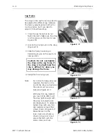
Page 77: ...he clamp If you NEED excessive force to close the clamp you have moved the spindle too far Loosen the lower nut and reverse the process 5 With the clamp closed try to move the spindle up and down If the spindle moves go to step 1 and repeat the procedure Clip Posts The clip posts are where the clips are attached when hooping a cap The posts are extendible and should be extended fully into the crow...

Page 78: ...nd the clip is difficult to close you may damage the frame 4 Retighten the 2 wing nuts Note For normal to heavy duty cap materials the latch on the end of the strap is attached at the outer most two screw holes see Figure 4 11 With very thin cap material you may not be able to get the strap tight enough with the wing nut adjustments described above To obtain a tighter strap with very thin cap mate...

Page 79: ...g Adjustments Only 3 27 I Interface PCB 2 14 J Jump Stitch Solenoid 3 16 Adjustment 3 17 Bracket Positioning 3 18 Plunger Positioning 3 17 Replacement 3 16 K Keyboard Display Replacement 2 2 L Lamp Assembly 2 4 Lint Wiper 2 21 Low Voltage Driver PCB 2 14 M Maintenance Philosophy 1 2 N Needle Bar Associated Parts Replacement 3 12 Needle Bar Guide Shaft Reciprocator Replacement 3 20 Needle Case 3 9 ...

Page 80: ...ip Posts 4 3 Driver Bar Cable 4 2 Spindles On The Clamps 4 3 X X Beam Assembly 2 17 X Drive Belt 2 19 Replacement 2 19 Belt Tension 2 20 X Motor Replacement 2 17 XYZ Motor Driver Amplifiers 2 15 Y Y Drive Belt 2 25 Replacement 2 25 Tension Adjustment 2 28 Y Motor Belt Tension 2 23 Replacement 2 21 Z Z Motor Belt Tension 3 3 Replacement 3 2 Z Shaft Encoder 3 4 Introduction 3 4 Inspection 3 5 Instal...

Reviews: