Power Distribution Section
This section is comprised of various functions including power entry, line filter, and
switching circuitry for 110 or 220 volt operation. The various voltage sources for
logic circuits, motors, and solenoids are integrated into the power distribution
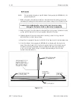
module. Additionally, the e-stop controls are built into the PCB located in this
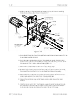
module (see Figure 2-9). The section is located under the left rear table top.
Voltage Adjustments
The voltage values are set at the factory and are regulated within the operating
ranges of the peripheral. NO further adjustments are required for voltage values.
Should any voltage drift out of its operating range, the module must be replaced.
Remove Table Top
To access the power distribution section for replacing the power module, remove
the left rear table top (with optional bobbin winder assembly) described as follows:
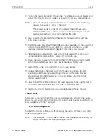
1. Loosen the left rear table top (with optional bobbin winder assembly) by
loosening the 4 truss screws (2 at the front and 2 at the rear).
Caution: If the optional bobbin winder is installed, you must
disconnect the two harnesses going to the bobbin winder assembly
as you lift the table top upward.
2. Lift the table top up and disconnect the bobbin winder harnesses if the bobbin
winder assembly is installed. Remove the table top to a safe storage area.
Module Replacement
The power distribution module is replaced as an entire assembly regardless of which
of the areas included within the module is malfunctioning. To replace the module
refer to the following steps:
1. Turn OFF the peripheral and unplug the power cord from the source.
2. Refer to the procedure for removing the left rear table top (with optional bobbin
winder assembly) and remove the table top.
3. Remove the five truss head screws and the left side cover of the peripheral to
enable access to the power switch harness connector shown in Figure 2-9.
4. Refer to Figure 2-9 and remove all of the harness connections entering the power
distribution module. In addition to the three harnesses entering the top and the
power switch harness at the side, there is a ground wire attached to a stud near
the rear left corner of the power distribution section that must be removed.
2 - 8
Power Distribution Section
EMT 1 Technical Manual
Melco Embroidery Systems


