3. Refer to the Caution statement at the beginning of this procedure and be certain
the Y drive belt in the other Y carriage is secure and with some amount of
tension.
4. Move the X beam to the rear until it mechanically stops.
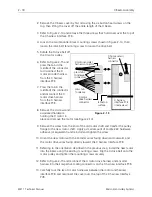
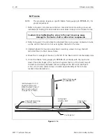
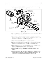
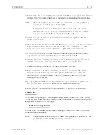
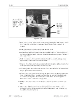
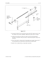
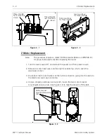
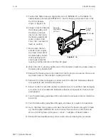
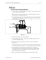
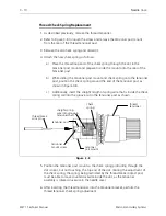
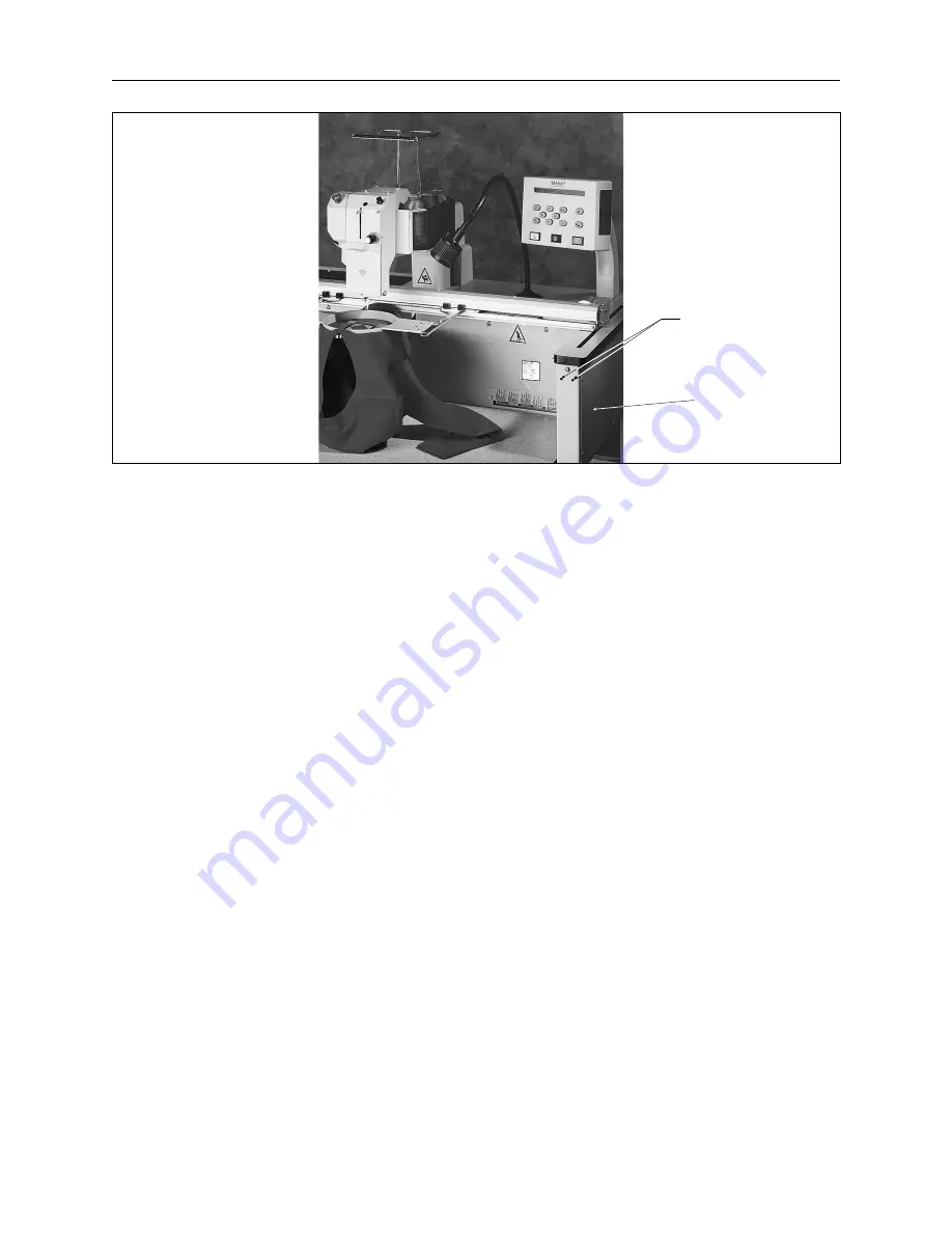
5. Position a hex wrench through the access hole (see Figure 2-19) and into one of
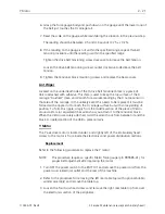
the two cap head screws in the front of the frame for adjusting the belt tension
(see Figure 2-20).
6. Note the location of the wrench handle and rotate the socket head cap screw
approximately 3 revolutions counter clockwise.
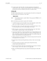
7. Move to the other access hole associated with tensioning the belt and rotate that
socket head cap screw the same amount as the first.
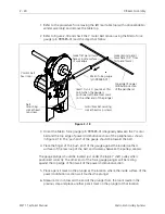
8. If replacing the Y drive belt on the left side of the peripheral, remove the Y home
flag to gain access to the belt clamp.
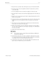
9. Push the now slack belt aside far enough to get a hex wrench through the access
holes in the base of the Y carriage mounting bracket and into the socket head
cap screws securing the Y drive belt to the under side of the Y carriage block.
Remove the screws and belt mounting clamp.
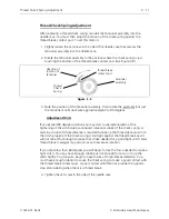
10. Slide the old belt out from around the two pulleys and prepare to install a new
belt.
11. Place a new belt into position around the pulleys and attach the belt to the
under side of the Y carriage block by reversing the previous steps for removing
the belt and mounting clamp.
right
side
cover
right side Y
belt tension
adjustment
access holes
the left side cover
and Y belt tension
adjustment access
holes are a mirrored
duplicate of the
right side
Figure 2 - 19
2 - 26
X Beam Assembly
EMT 1 Technical Manual
Melco Embroidery Systems


