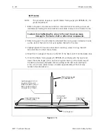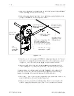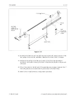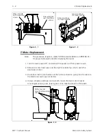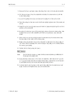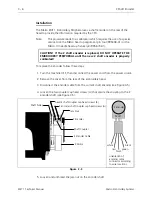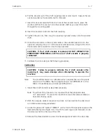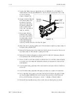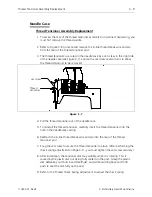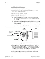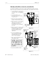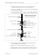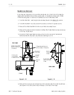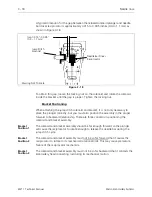
5. Remove the four cap head screws attaching the motor to the bracket standoffs.
6. Lift the motor away from the standoffs and allow the drive belt to slip off the
motor drive pulley.
7. Loosen the pulley set screws and remove the pulley from the motor shaft.
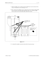
8. Place the pulley on the new motor shaft and slightly tighten one of the pulley set
screws.
9. Slide the motor mount bracket up and hold it in place while placing the motor in
position at the standoffs.
10. Be certain the bottom loop of the drive belt is below the motor drive pulley, then
reattach the motor to the standoffs with the four cap head screws removed
earlier.
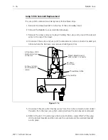
11. Allow the motor and mounting bracket to slide down as the drive belt catches
the assembly in the center of the drive pulley.
12. Make certain the bottom loop of the drive belt is centered in the drive pulley. If
not, loosen the drive pulley set screw and adjust the pulley so it is directly below
the main Z drive pulley.
13. Tighten both Z drive pulley set screws.
Belt Tension
Note:
This procedure requires a Gates 5M Tensiometer (Melco p/n 992165-01)
for proper belt adjustment.
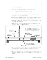
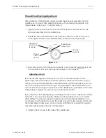
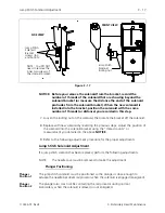
14. Apply downward pressure on the motor to establish a belt tension of 7 pounds
(+/- 1 pound) measured with the Gates Tensiometer. Tighten the motor bracket
mounting/tensioning nuts while maintaining the belt tension.
15. Connect the Z motor harness to the end of the cable from the electronics card
cage connector and replace the covers removed earlier.
Belt Tension
3 - 3
110344-01, Rev B
3. Embroidery Head Maintenance

