1.0
Operation
The unit’s design is a "modular" concept. All controls and outputs are clearly marked and
logically grouped so continual reference to the instruction manual should not be necessary once
the test operator is acquainted with the operation of the test system. The unit’s rear panel will
appear different among units since each unit may have up to four V/I Generator Modules and
may have an optional EPOCH II / EPOCH 20 interface, or other type. However, there must be at
least one V/I Generator Module installed for this unit to operate properly.
1.1
Control Description
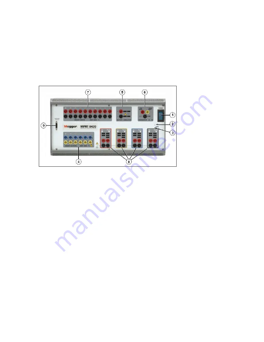
Figure 1 MPRT Front Panel
1.1.1
Front Panel
1.
POWER ON/OFF Switch
– used to switch unit on and off.
2.
ON Light
– indicates power is on when illuminated.
3.
Reset Button
– the reset button provides a soft reboot for the unit and restores the unit
to its normal Power-On state. The reset will clear all values entered into various screens.
The data should be saved before performing a reset, if possible.
4.
Binary Outputs
– there are 6 internal to the MPRT Unit. Each output can be configured
as Normally Open or Normally Closed contacts providing logic to the device under test.
The output can switch up to 300 VAC or 250 VDC with 1 Amp continuous. The
programmable wait duration is from 1 millisecond to 10,000 milliseconds.
5.
Battery Simulator
– the output voltages are 24, 48, 125 and 250 Volts DC with current
limiting output power protection. If a voltage is powered ON, that respective voltage will
have a lighted value.
6.
Measurement (DC IN)
– the DC IN will allow measurements up to
±
10 Volts DC or
±
20
milliamps of current.
7.
Binary Inputs
– there are 10 internal to the MPRT unit. The input will accept a voltage
range of 5 to 300 VAC or 5 to 250 VDC or dry Normally Open / Normally Closed contacts.
8.
Three Phase Power Indication
– the three phases are noted by the red, yellow, and
blue color boxes surrounding each output. Phase A (V1 & I1) is denoted by the red color;
11
www
. ElectricalPartManuals
. com


