


MAX32660 User Guide
Maxim Integrated
Page 138 of 195
For applications where an external device may hold the SCL line low longer than the maximum timeout supported, the
timeout can be disabled by setting the timeout field to 0 (
to
= 0).
12.6
I
2
C Addressing
After a START or RESTART condition, an address byte is transmitted where the first seven bits are the address, and the last
bit indicates to the slave if the operation is a read or a write.
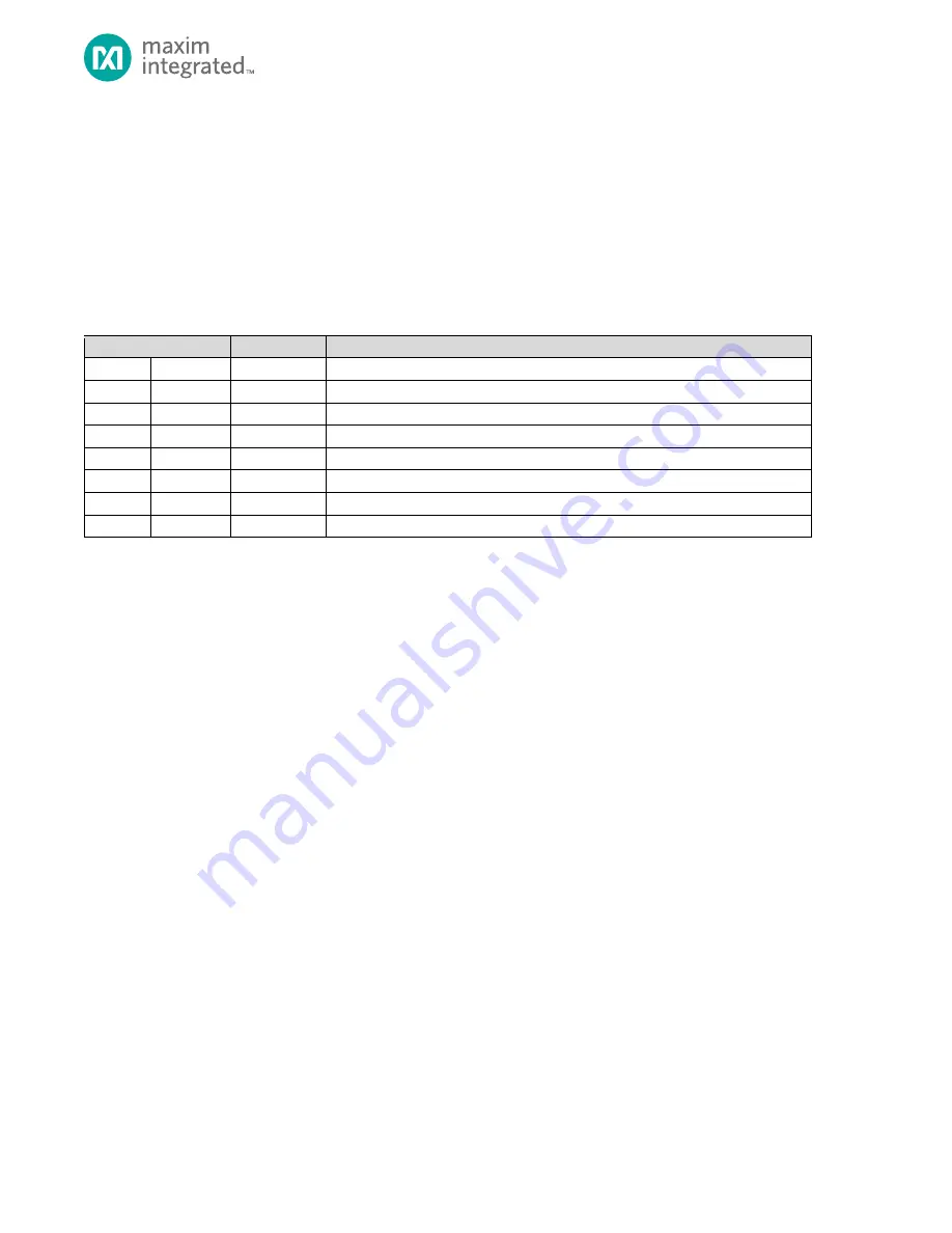
Table 12-2: I
2
C Address Byte Format
X=Don’t Care
Slave Address Bits
R/W Bit
Description
0000
000
0
General Call Address
0000
000
1
START Condition
0000
001
X
CBUS Address
0000
010
X
Reserved for different bus format
0000
011
X
Reserved for future purposes
0000
1XX
X
HS-mode master code
1111
1XX
X
Reserved for future purposes
1111
0XX
X
10-bit slave addressing
In 7-bit addressing mode, the master sends one address byte. To address a 7-bit address slave, first clear
sea
= 0, then write the address to the TX FIFO formatted as follows:
Master write to Slave : 7-bit address : [A6A5A4A3A2A1A0 0]
Master read from Slave : 7-bit address : [A6A5A4A3A2A1A0 1]
In 10-bit addressing mode (
sea
= 1), the first byte the master sends is the 10-bit Slave Addressing byte
which includes the first two bits of the 10-bit address, followed by a 0 for the R/W bit. The master then sends a second byte
representing the remainder of the 10-bit address. If the operation is a write as indicated by the R/W bit in the second byte,
the data is transmitted to the slave for the write. If the operation is a read, as indicated by the R/W bit in the second byte,
the I
2
C master performs a REPEATED START and transmits the 10-bit slave address again with the R/W bit set to 1. The I
2
C
peripheral hardware then begins receiving data from the slave device.
If the RX FIFO is not empty and an I
2
C write occurs, the I
2
C peripheral hardware automatically sends a NACK.
The setting of the Do Not Respond bit (
dnr
) controls when a NACK is sent as follows:
•
dnr
= 1
−
A NACK is sent on the first address byte received and the hardware sets the Do Not Respond Interrupt Flag
(
dnreri = 1)
•
dnr
= 0
−
Sends an ACK for each address byte, but NACKs subsequent data received.
If the TX FIFO is not ready (
.txrdy =
0) and the I
2
C controller receives a data read, the hardware automatically
sends a NACK during the first address byte. The setting of the Do Not Respond field is ignored by the hardware for this
condition because it is the only opportunity to send a NACK for an I
2
C read transaction.


