24
3.2.
Stationary beacon
-
Usually mounted on walls or ceilings above the robot
with ultrasonic sensors facing down
—to provide the
most robust unobstructed ultrasonic signal coverage
to the robot. However, for automatic landing and
indoor navigation of copters, for example, it is
recommended to install mobile beacon horizontally
on the belly of the copter so that the beacon would
be looking downwards
-
The position and orientation of the beacons should
be chosen in a way that provides maximum
ultrasonic signal coverage. System efficacy strongly
depends on the quality of ultrasonic signal
received by stationary beacons
-
Stationary beacons emit and receive ultrasound during the map configuration
period. In non-inverse architecture once the map is formed and frozen, they only
work as receivers. In inverse architecture they only work as transmitters.
-
Stationary beacons have no exterior differences with regard to mobile beacons
-
The mobile and stationary beacons can be easily interchanged during configuration
in the Dashboard
-
There are 433MHz(out of production, get bug-fixing SW update only) and
868/915MHz versions available. A proprietary radio protocol is used for
communication and synchronization. Other ISM bands are available upon request
as well
-
Stationary beacon can be equipped with full-size 165mm antenna , which provides
more robust radio connection between modem and beacons.
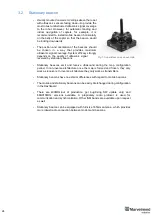
Fig.1: Super-Beacon as an example
Summary of Contents for IA-04-2D-Badge
Page 1: ...Marvelmind Indoor Navigation System Operating manual v2022_08_24 www marvelmind com ...
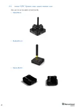
Page 21: ...21 Beacon Mini TX Beacon Industrial RX Beacon Industrial TX Metal ...
Page 22: ...22 Industrial Super Beacon Plastic ...
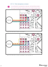
Page 39: ...39 Figure 7 One External Microphone connection Figure 8 Two External Microphone connection ...
Page 44: ...44 Figure 3 One external microphone soldering Figure 4 Two external microphones soldering ...
Page 46: ...46 Figure 7 Two External Microphones final view Figure 8 Two External Microphones final view ...
Page 118: ...118 6 6 28 The system is now fully operational ...
Page 180: ...180 Floor 5 is enabled Floor 4 is enabled ...
Page 190: ...190 Z X ...
Page 207: ...207 Choose color and press OK Color applied Now background matches floorplan ...
Page 214: ...214 9 24 IMU axis positioning Super Beacon IMU axis positions HW v4 9 IMU axis positions ...
Page 215: ...215 Mini TX IMU axis positions Mini RX beacon IMU axis positions ...
Page 219: ...219 Real time player turned on ...
Page 223: ...223 10 2 Beacon HW v4 9 external interface 4x4 pinout top view ...
Page 224: ...224 10 3 Modem HW v4 9 external interface pinout top view ...
Page 232: ...232 If everything done correctly Own IP address will change Static IP settings completed ...
Page 238: ...238 How to change modes Choose hedge Go to Ultrasound TDMA mode Left Click to change ...


